Sunday, December 30, 2012

Moose I denn

In case you arewonderig about the title of this post, there is an old German folk song which begins like this:

    Muss I denn, muss I denn/ in Staetle hinaus....

This is old German and dialect at that. But it sort of sounds like moose. And it is time for the obligatory moose picture. Before Christmas I espied a branch moving to and fro. No wind. Said I, "either Sir Isaac Newton was full of garbage or there is a moose in the yard. Happily for physics, it turned out to be the latter. The culprit was a youngish moose. Not two meters from the window. Close! Thanks to John for the photo.

It is very nice to have moose in the yard. Gentle giants. This one is quite young. Recently cast off by mommy and left to his (her?) own devices.

Happy New Year! You too, mooses.

Sunday, December 16, 2012

Gearing up!

John has decided that Chalupy acres has a tutelary god. That's the good news. The bad news is that his name is Sisyphus. He was the one that kept rolling the stone up the hill, only to have it roll over him before he got to the top. In this matter of gear-cutting old Si has been right up to scratch. OK, so far we have made a dividing plate. We even have a blank gear at hand. The big moment has arrived. We must make a cutter to the correct profile.

Now the subject of gear profiles is somewhat controversial and quite mathematical. But I propose to avoid this as much as possible, although the practical details are really not that complicated. I am trying to cut clock gears. These are "cycloidal" profile gears but you can ignore that. Thing is you have to do is shape a cutter to the correct profile. You can work out that profile. The tip of the tooth is curved. And so I went through a bunch of calculations and came up with a radius of curvature for which I happened to have a diamond tool. And behold, Sisyphus came in for a visit. I proposed to cut the cuttter with the same setup used to cut the gear;  i.e my DSO (Dremel-Shaped Object) in the vertical slide on the lathe. My carefully chosen cutter would'nt stay put in the DSO! The shank was defective. The shanks are 6.3 mm which I suppose is some fraction of an inch in RGU, but the shank was 5.95 mm and the DSO collet wouldn't grab. Curses!

So what I did was to take a radius much too large for the occasion. It was all I had; it was either that or go online and order some diamond tools, which I will eventually have to do. But not right now, please. What I wanted to do is convince myself I could cut 30 teeth in a 30 mm or so blank. So I ground up a cutter, in the lathe itself. Its radius is twice what it should be. But it will do for now. All I'm after is feasiblity. Above is the cutter as ground. It is being held in an arbor I had to make, held by a setscrew. The arbor is a piece of hardware store rod. The cutter itself is a piece of Dremel tool, broken or worn down, from my scraps. Dremel tools are very nice and hard. Just the thing for a cutter.

Now, Houston, we have a cutter. Next  step is to set up the divider. We must make sure the teeth of the gear are uniformly spaced. So the divider plate comes into action.
The divider plate is held steady by a springy piece (old strapping tape) with a pin affixed. We index to the #1 hole. Since I am cutting thirty teeth, and the divider has 60 holes, I have to skip one hole for every tooth in the gear. This requires some concentration. Note I have removed the drive belt from the lathe. This is a safeguard against accidentaly turning on the lathe! (I did that too. Disaster. Go away, Sisyphus!)

Next we use our previously made arbor (read "axle") and bolt our gear blank into it.
With the vertical slide micrometer feed we painstakingly adjust the cutter height to the center line of the lathe. The proto-gear is being held in the 3-jaw chuck. It should be held in a collet. Don't have a big enough collet. Too bad. Now we turn on, not the lathe, but the Dremel. With the cross-slide, advance the tool until it cuts. It cuts amazingly well. Since the cross-slide is calibrated you must note how far you advanced (actually retracted) it. This gives you depth of cut. I was none too careful about this. In about two seconds the tooth is cut.


Now it is routine. "Index" over. Skip one hole on the dividing plate, remember? Turn on the DSO. Do not turn on the lathe. That's why I took off the belt. Crank cross-slide in. Remember to what number you must crank it in. Oh, you forgot? Gear won't work. But this does not matter for now. We are, literally, cutting our teeth. When I had done all the 30 holes I had an object that looked remarkably like a gear.
 

I am very pleased. The whole lashup -- the DSO held to the vertical slide, the homemade divider plate, the primitive index pin -- it all worked. The cutter was all wrong for reasons given. But all the things I was worried about -- wobble, for instance -- did not materialize. Maybe brass would have failed, but since I am planning on plastic gears, this will not matter.


Wednesday, December 12, 2012

Divide and conquer

OK, I confess. What I am really trying to do is build a clock from the ground up. As with anything else, building a clock is no mean feat. It also rapidly becomes an obsession. So I am obsessed. I do not think this is grounds for a lawsuit. Anyway, the big thing about a clock is gear-cutting. There are several requirements for this. You need two perpendicular axes. On one of them a cutter is revolved, preferably by power. On the other, the would-be gear is held. On this latter you must have an indexer of some kind, i.e. a gizmo that will turn the (proto)gear by a precise amount. In a previous post I chronicled the making of the latter gizmo, the dividing plate. The gizmo allows me to divide a circle into 60 parts. By skipping holes I could also do 30 parts. In fact, any of the factors of 60, and now you know why they made you study factoring in school. Clock gears go from 120 or so teeth all the way down to 6. A clock, you see, is just a big gearbox. But you cannot shift the gears, unlike an automobile.

So in our last episode I had made the dividing plate. Had I about $300 to spare I could have bought a spin indexer to do the same job. But no. We did a dividing plate by hand (previous post).  So I turned up an arbor from a piece of scrap steel. An arbor in machinistspeak is simply an axle. There it is on the four-jaw chuck, a pain to set up but it runs really really true.  This held my victim, a failure from the dividing plate episode. Much too small to be a dividing plate. Next, I  arranged my Dremel (knock-off) device on to the vertical slide on the lathe. Major project. Too many things to adjust. I have blogged on this contraption before, so see previous posts.

This needs some overhauling. Once the DSO (Dremel Shaped Object is bolted in I cannot adjust it except with the vertical slide, and it has extremely limited travel, 50 mm or so. Not enough. This is why most people do this on a mill. But a (small) mill is about $500 plus shipping, almost as much as the mill itself. And again, I have no space for a mill. But lashup though it may be, I have the two required perpendicular axes. And it cost much less than the mill, i.e. zero.


I have no cutter yet. This is work in progress. In its stead (thak you Richard, for pointing out my error. I said "staid" before),  I put an abrasive cut-off wheel on the dremel. I also arranged a spring-loaded detent for the divider plate. So I am really not cutting gears yet. But the whole two-axis lashup arrangement is working! I cut some remarkably gear-like slots in the sacrificial victim! I was a bit worried about wobble, but none was perceptible.

The classical material for clock gears is brass, sometimes steel. But brass is like Unobtainium in Alaska. Small pieces, at a hobby store, maybe. Big pieces, no. So I am doing all this in plastic. Plastic is everywhere. On dismantling an expired (battery) clock I found plastic gears everywhere. So if they can do it so can I. My  plastic is found. I think it is a piece of refrigerator. So I can experiment all day long. Just as well. Winter is here. Lots of time to experiment.

Sunday, December 9, 2012

It snows in Alaska

One of the more surprising facts of Alaska is that it does not snow that much. Not here, anyway. If I lived in Cordova that might be false, but no. I am in Willow. We had 12 cm of snow on the official snow pole. But last night in came down. I awoke this morning to find 29 cm on the OSP. That stands for Official Snow Pole. It is a broken ski pole. To this, via epoxy,  I affixed a large nail that allows me to sink it in the ground. I have marked it in 10 cm intervals. So, the OSP reports 29 cm. I record its readings daily. Usually zero this time of year. So 12 to 29 is some 17 cm of snow. Convert it yourself; I refuse to deal with King Henry's thumb width units.


Anyway time to clea the driveway.  John and Fluffy went out and played in the snow. Fluffy threatened to throw snowballs at John. John, armed with mechanical contrivances, had the upper hand, for all he had to do was turn the chute of Horatio the snowblower in her direction and she would be deluged. But Fluffy is brave. She handled the snowblower like a pro.

 
John had more than his share too.

He plowed a trail around the house, most useful. I pleaded flu, but at least I went out for moral support and very glad I didn't have to do it myself.

Chalupy is now accessible. Very important in winter. More snow in the offing. We will deal with it.

Incidentally all the snowblower's problems were solved with a new sparkplug. Moral, from lawnmowers on up: change your sparkplug once a year at least. 

Sunday, December 2, 2012

Dremel attachment, the sequel

In our last episode we saw how I went about converting a chainsaw sharpening attachment into a vertical spindle for the Taig. But you will remember that the thing fouled the DSO (Dremel Shaped Object)/ What we needed were some spacers. Some careful measurement convinced me that 6.5 mm would be enough. I found a nice piece of scrap rod a little over 13mm long. Great. Now we have to center-drill it so it will act as a spacer. Of course it will need longer screws. Fortunately I save every screw that comes across my path.  But the real problem is center-drilling the spacers. Now the best way to do this is on the Taig, but Mr Taig was busy with other jobs. Furthermore the self-centering three-jaw chuck's jaws are shot. So I did it on the drill press. I made a fixture (a device to hold things down while you work on them). A simple wood block. Drill a hole through it, tight fit on the round piece, and slit the hole with a saw.


Clamp it in a vise. The slit makes the wood close around the steel rod and holds it fast.  Then you can e.g. drill it, which I did, all the way through. Fortunalely the hole was started by a previous project so I didn't have to center it. Then I sawed the spacer in half with a hacksaw, a marvellous tool. Use the same block to do the sawing. Guides the saw.  At the end of the day I had to roughly equal pieces. Trim up with a file, still on the block. At the end of the day I had two spacers.For the record the spacers are steel 6.3 mm (1/4") hardware store stuff.

You can just see the spacers. Now I have a spindle at right angles to the lathe axis, marvellous.

What I really want to do is cut clock gears. So for this I need a dividing plate and this is my next project. We will see how it goes.  I will also need gear cutters. I will have to make these. This is Alaska. We do have Home depot, and Lowe's, but we do not have machinist's supply houses. Got to order from afar, and pay shipping costs too. So I will make my own cutters. They must fit a Dremel shaft. I intend to start out with plastic gears.  Dremel will certainly cut plastic! But your high-precision  quartz clock uses plastic (probably lexan) gears so maybe I can cut one too.

I have also, quite accidentally, got the beginning of an ornamental lathe, but that's a separate post. Still need a dividing plate. Stay tuned.

Wednesday, November 28, 2012

A vertical spindle for the Taig lathe

Ah, what to post. I have been very busy, but as usual at this time of year I can't tell you about it. So let's look at the Dremel atachment for the Taig lathe. Nice and neutral, nobody's getting one of these for Christmas.

Milling on my Taig lathe is a comprehensive nuisance.  I do have the Taig vertical milling attachment.  But the cross-feed screw has a very limited travel. So I have been toying for a long time with adding a vertical milling spindle. A lot of things came together this afternoon. An article in Popular Mechanics, a reprint. A lot of watching videos on watchmaking, a fascinating subject. Need a magnifying glass!  All the reading I have done on ornamental lathes. Lots of stuff.

So a long time ago I bought an attachment for the Dremel. I don't own such a thing but I have a knock-off, made in Asia. Good for them. The attachment purported to let you sharpen chainsaws, a subject of great interest to me. Dull chainsaws are dangerous. Even sharp ones are risky, but less so. This attachment , as far as I am concerned, was a waste of money. It consisted of a bracket and a plastic gizmo that screws on to the nose of your DSO (Dremel-Shaped Object). You held the bracket so's it lined up with the bar, then used rotary grinders to sharpen the teeth. But hand-held. Waste of time. You cannot hand-hold these things worth spit. I have discoursed before on this subject. Get a proper jig, or buy a chain saw grinder. I did both. But the Dremel nose and the bracket I kept.

Today I thought, "hey, if attached this bracket to a piece of 1/4" (6mm) bar with some holes drilled into it, I could mount the whole thing on the Taig milling attachment! So after some work this afternoon, we are here.

Behold the Taig lathe with vertical milling attachment. Behold also the 6mm bar. It sticks up and fouls the DSO. But really the bracket is inadequate. The DSO won't fit.  A matter of about 3mm. So I will have to make some spacers. This will allow the DSO to screw into the plastic fitting at the bottom. This may turn into a major project. But if I can do it, then I have a vertical spindle for the Taig.  Maybe I could even cut gears, at least in Brass or  Aluminum or plastic.  Then I could make a clock. Of course I would need dividing  plates. Next topic, I suppose.

Sunday, November 18, 2012

Miracles with SuperGlue

I have this project. Unfortunately I cannot tell you why I have it or what its ultimate destiny may be. This is because what I am making could be for you! Keeping this blog going in the pre-Christmas months is a major headache. However, I can tell you this. I am making bearings. I have drilled out some steel rod to 3.15 mm which is some RGU. Now I have to cut a slot in the rod. I must mill this slot. I have the Taig lathe (on which I turned the bearings). I also have the vertical milling attachment. I refuse to buy the Taig mill. For one thing it costs $600. For another I have no place to put it! So we must make do with what we have.

For those of you who do not know the difference between a lathe and a mill: in the lathe the work rotates. The cutter stays put. So you turn objects of rotational symmetry, like cylinders. A mill works backwards. The cutter rotates and the work stays put. Aye, and there's the rub. Keeping the work put seems to be 99% of milling. So I have this cylinder, drilled out; I want to cut a slot in it along the long axis. Conventional wisdom says put I the cylinder in a V-block. Clamp it down. Yes, but my V-block clamp fouls. It hits the lathe, the chuck, everything. Can't do it. What now?

So there is a solution. Use super-glue! I actually super-glued the cylinder to the V-block. Then I clamped the V-block onto my home-built milling table. The aluminum clamper is starting to bend; must replace it with steel. No matter. It worked. I move the whole milling table up and down with its feedscrew. I am using a Taig milling cutter, about 1.6 mm wide. The Milling cutter is held by a Taig collet and I must say this is the first time I have found the Taig collets useful. They usually are either too small or too large.  Anyway, note the slips of paper between the clamping fixtures. These keep things from slipping and are very effective. Thanks to Myfordboy for that tip. See his blog, cited off this one.  Great source of information.

So I cut my slot. A bit too deep, but I can deal with that. Another use for my leadscrew, when I get it done.  Really have to hand it to superglue. In the end, superglue can be undone with heat. Just heat up with a butane torch.  Modern adhesives are a lifesaver.

Saturday, November 10, 2012

Chasing the elusive thread

I knew I had a label for it. Screw chasing, that's what it was. Took forever to find it though. So today's post returns us to March and April of last year. When summer comes I move outdoors so nothing got done since then. Well, I watched  lot of thread-chasing videos on YouTube and I must say I admire the dexterity of these people, not to mention the fact that they put their knowledge out on the net for all to see. Generous to a fault. Anyway, you will recall that this label deals with cutting threads in wood. The methods range from ancient Greek techniques (cut thread with chisel) to wood taps and dies and finally chasing on a lathe. Since I want to use my Polecat this is not a trivial undertaking.


You will also recall I am cutting a 4mm pitch thread. This is very large. Most of the people on You Tube are (a) using powered lathes and (b) cutting something like 16 TPI or 1.6mm pitches. So you might say I am behind the power curve, since the smaller the pitch the easier to chase. However, we press on. We have evolved an intermediate technique. It is somewhere between the Greeks and the modern chasers. So we start out in Greek style, wrapping a piece of paper marked off in 4mm lines. It must be offset when you wrap it by one interval or you will cut circles.

Tape the paper down to your cylinder really well. else it will slip and make hash out of your efforts. Now, just like the Greeks, take your mini-dozuki saw and saw out the lines, rotating the lathe by hand. Do not try to treadle.

You do not have to saw very deep but you have to saw very carefully indeed. You must hold the saw along the lines of the spiral. Now we want to deepen the groove. For this I find the skew chisel is just the ticket, held vertically for a change.
It is important that the tool be at center height. Nice thing about having the work between centers is that you can rotate it at will. Thus we clean up small mistakes in the sawing. We get the groove as deep as we think it needs to be. So that the next tool has a path to follow. Next we really start chasing the thread.
Here is my one-point chasing tool which I cobbled up from an old piece of steel. It has a 60 deg. point. Modeled on a machine lathe thread-cutting tool. It also has some side relief. Probably not enough. Still experimenting. But we still do not treadle. We apply the tool and start forming the thread, also deepening the groove. Turn by hand.

When you get the groove deep enough you will find you can actually treadle; the tool will follow the groove all by itself. Not only that, the multi-tooth chase actually works! See previous posts. But you must treadle very slowly. This is hard to do. The temptation to bash the treadle down is overwhelming. Resist it. Any machinist knows that to cut a thread you put the lathe in backgear and take the slowest speed you have. I have no backgear, it's all my leg. It is all too easy to have the tool jump out of the groove, or dig in.

The above shots were staged for the blog. When I was working this out I had no thoughts of taking pictures. But at the end of the day I had cut a quite respectable thread on the left end of the turning.
There are problems. For one thing the cylinder has a big crack in it, making things difficult. For another it chips. I think this is a problem with the paper guideliner. Lines not exacty spaced. I can fix this. It is also a problem with my one-point chaser, I think. Need more side relief, or is that side rake? But I can now say I chased a thread on a pole lathe. Stay tuned, as usual.

And at last we have snow on the ground. Not much, about 2cm. Enough to ski on! I was so tired of walking.

Wednesday, November 7, 2012

Steady part 2.

Still on the subject of steady rests for turning long whippy pieces. Now a lathe will turn to about .02 mm or a "thou," .001 of the width of Henry VIII's thumb. What a remarkable choice of a unit. Still, in those days the King's word was the law and we have not progessed much beyond that. Anyway, when you are turning long thin pieces the whip or spring in the piece far exceeds the accuracy of the cut of the lathe. If your lathe is good to .02 mm the thing will spring a whole mm so your accuracy is gone.

So I am trying to turn the threads off of a 1/4" threaded rod. My whole objective, as I related before is to put a leadscrew on the Taig lathe to allow me  precision adjustment along the bed. Taig uses a rack-and-pinion arrangement; cheap but inaccurate. But a 1/4 (6mm) rod is very whippy. I would rather use something around 18mm but I can't fit that through the bore of the Taig. So in this case we need steadies, and you might want (or not, but I will give it to you anyway) to see the completed arrangement.
 
We have both a fixed steady rest, which I described before, and a traveling steady bolted to the carriage. Both of these arrangements need refining, but they work. The traveling steady is a casting supplied by the Chalupy foundry, AKA John, but I did the pattern. And poorly. The more work you put into a pattern (wood) the less metal you have to move. Lesson learned.

The real problem in these rests is to machine the slots for the crews that hold these things down. In fact, the whole problem of machining metal is holding the work. The actual machining is easy, if only the work will stay put. So after many trials, unseemly language, and agony I came up with something that worked.

Here it is. The Taig has been fitted with the vertical milling attachment. An end mill sits in the 3-jaw chuck. An aluminum bar and some long screws provide vertical steadiness. Two pieces of steel square, barely visible, are held by clamps to my horizontal table. They keep the work form rotating around in the table. I wish I had an end mill exactly the width of the slot, but I broke it. You are not supposed to hold an end mill in a chuck but needs must when the Devil drives, as they say. You should use collets. But none of the Taig collets will hold my end mills. So into the chuck it goes.

 I finally got the blasted screw turned down. But alas, at last minute something went wrong and the hole in the mounting to pass the turned-down portion went wayward. I am in to re-making the mounting. Grrr.

After all this precision work it was comic relief to get Polecat, my mini-pole lathe (bungee lathe, actually) running  again.

It is nice. No motor. No fussing.  Immune to power failures. Excellent cardio workout. Just turn the thing! Made some improvements.


Polecat is doing a tool handle, of course. That's why I built it. Never can have enough tool handles. The handle happens to be for an Ulu. Whose? Ah, I won't tell.  Eat your heart out.

Sunday, October 28, 2012

Steady there! Rest.

I own a Taig (q.g) microlathe. It is about 60mm center height and about 30 cm bed. It is enough for me right now, and it fits in a very small space. Now I am adding a feeedscrew (or leadscrew)  to it, following a detailed recipe at Dean Williams's page (look under leadscrew) out there on the web. A feedscrew is a long screw that allows you to traverse the carriage of the lathe by controlled amounts. Dean calls for a 1/4-20 left-handed thread; but I am using an ordinary hardware store threaded rod. Well, at some point the recipe calls for me to turn the threads off the rod. There came the rub. When I got the rod into the lathe the thing whipped around like an enraged Anaconda and bent the rod beyond repair. Now all machinists -- I am a very indifferent one -- know you can't turn long whippy stuff without a steady rest. A steady rest is just a set of fingers in a frame. Taig will sell you one, but I follow George Dyson's principle: never buy anything you can make, and never make anything you can find. Well, I did not think I'd find a Taig steady rest on my walks, so we begin the odyssey.


I happened to have the Taig wood-turning base and some wide flat (about 50mm) aluminum stuff, and that seved as a foundation. I drilled two holes for #4-40 screws in the aluminum flat, and then transferred them over to the wood-turning base. I drilled and tapped the base for 4-40 screws, a ticklish operation because it is very easy to break a 4-40 tap. It is about 3mm across. But I did it. I also drilled the biggest hole I could in the Al bar. 3/8 RGU. It will pass my feedscrew and that is what I want. Eventually I will drill it out larger, but for now it will do. The bar bolts on to the base with capscrews. If I want to turn wood I just have to unscrew them.

Now we have to make the fingers. Classic is brass. Don't have any in the right size. Use Al instead, something like 1/2x1/8  RGU hardware store stuff. Cut it with a hacksaw. Now we need slots in the fingers so we can adjust them to fit the work being turned.

I drilled a row of holes in the proto-finger. This leaves a whole bunch of metal as webs.
So I did something that the books do not advise you to do. I chucked a small endmill in the drill press and removed the webs by hand. Very difficult because my drill press does not have a quill lock. But I did it!  I do have the milling head for the Taig, but holding the work is 90% of milling and I cannot hold those fingers in the milling attachment at this time. At the end we had a quite respectable steady rest.
The slots on the fingers slide over 8-32 capscrews. Get your piece chucked, slide it through the hole in the upright, tighten up the fingers. I now have a new problem. I bought a bunch of fasteners in various sizes, mostly capscrews. Now where shall I store them? Ah, problem solved, problem created. But I have had lots of tapping practice. You can read all about tapping on the web, and in books, but there is no substitute for experience.

And of course this gadget had to have a name. Behold Steady Eddie. Long may he hold long whippy things.

Thursday, October 25, 2012

Machine shed: done deal!

The machine shed is done! The next-to-last step was to roof the thing with castoff tin.Then we moved the lawn tractor and the tiller in with them.
 
As a super step, we had a bunch of spare tarps and cutoff tin. John hung them up as protection from the snow. We feel very rich. The shed is literally a lashup, but  it will keep my machines out of the snow. Now I have to remember to drain all the gas tanks. I have just posted this on our chore list. If you leave gas over winter in your smaller machines you will get gum and varnish all over the innards. Especially the carb. I add gas stabilizer to my small-machine reserve, which helps prevent the condition. Still better safe than sorry.
 
Anyway, the machines, for the first time in Chalupy history, are under cover. Happiness is a rough and ready machine shed.

Sunday, October 14, 2012

Machine shed, rough and ready

I started the summer with dreams, nay, a design, for a timber-framed machine shed/blacksmith shop. We would saw the lumber with an Alaska mill, and mortise-and-tenon the joints. Alas, the summer is gone, and nothing done. All kinds of things got in the way, from chain saw failure (Siegfried started to choke. Needs new points, probably, but hard to find) to  the Snow Splitter, which was really the priority project. Of course everything took longer than expected. So, time for plan B. We will throw up a rough and ready shed. Really rough. 5x5 meters. Low ends 2 meters, high ends 3 meters. All such projects begin with holes in the ground.
 John kindly dug the holes, 60 cm deep. We have put poles in the holes. This involved a trip to the woods and a chain saw. We got most of the poles within 100 meters of my property. We did not peel them. Hey, this is really rough and ready stuff. Next job is to nail crosspieces to the uprights. We do this on the ground. Then we lever up the structure into the holes, a la Pennsylvania barn-raising. An auf! (on up), say the Amish.


Next job is to add rafters. The rafters, of course, must be a bit longer than the five-meter length of  the shed. A trip to the woods, a chainsaw, something of an eye for what's too heavy and what isn't, and we are done.

And another view. At the lower end, the thick end of the rafters, lashings are in order. Nails not long enough, unless you use "cabin spikes" (which we used to nail the crosspieces down) and even then you have to drill holes. Thank heavens for cordless drills. 
You can see the rafters in the above shot a little better. We will nail "nailers" (crosswise to the rafter strips) to the rafters and then use castoff "tin" (really galvanized steel) available at your friendly Ghost House for free.

Now comes the icing on the cake. It snowed last night. But Lysander the heroic tractor must be gotten under cover. I agonized all morning. Can I get him to start? Almost didn't dare try. Haven't run him for over a year. Just in case I charged up Lysander's battery. It is an old 6-volt system with positive ground. Yes, positive. Lysander was built in 1941. You can tell by the serial number. So I took my courage in both hands and went on with the starting drill. Pour gas into the tank. The gas is old. It has been stabilized, but it is still two years old. Worry about it. Hook up the battery.  Remember + is ground! Take off the glass crud filter and clean it. Drop the nut on the ground and spend an eternity fishing it out. Turn on gas. Pull out the switch. A major project. Needs pliers. Pull out the choke. This thing has not started for about a year and a half. Give it a shot of ether into the air intake, cheap insurance. My fingers are freezing.  Climb up into seat. Make sure it's in neutral gear. Push in clutch. Push starter button. Lysander turned over. Black smoke from exhaust. Sput sput. Too much gas. Push in choke. Try again. Roar! Ran a little rough at first. So would you if you were over 70 years old and hadn't worked out for over a year. Then it settled down into a lovely Lysander rumble-roar. I cannot believe how well this machine is built. Anyway I drove him into the shed. I think he looks very happy there. When the pic was taken he was still running. He has a generator problem. Won't charge battery. Must worry about that, but not today.
 
Personally I think Lysander likes his new home. But this is sheer anthropomorphism. It's just a machine. Or is it? As Roger Welsch (q.g.) sagely  remarks, could it be that tractors have (gulp) souls?

Friday, October 12, 2012

Moose in the yard, as usual

 It is fall. Hunting season is over. Somehow the moose know that, and they are starting to reappear in the yard. Now, if I could only get them to trim the lawn... but anyway, look, Ma, there's a moose in my yard!


Originally there was but one. One is a male. He has one small horn. Then we had three. I suspect that they are a family. Mommy to the left; son center, daughter right. I took this picture through the mosquito screen in the living room, a bit blurry. Sorry. Well, they are mowing the lawn, in a sort of mooseish disorganized manner. So I dashed outside, braving the -7C temperature. I got a slightly clearer picture.

I took a bunch of other pictures. No doubt the camera was mad at me. Point and shoot, they say, but they say nothing about whether you have all the complex settings in the camera correct.

But anyway, moose are fun. Don't get too close to them. They can trample you to death. And as I write this there are two more moose in the yard. My camera is out of battery. That kind of a day. These are a different set. Much darker than this morning's group. Definitely a moose day at Chalupy.

Sunday, October 7, 2012

The snow splitter project revealed

In winter, the snow accumulates on the roof. Eventually, a warming combined with gravity gets it loose. With a crack of thunder it slides off the roof, and I am blocked in. Hours of shoveling. The snow blower won't touch it. It's so hard you need not just a snow shovel. You need an ice axe, the Dragon Lady, and divine providence to be rid of it. So, in the depths of last year's winter, the Snow Splitter project was born. The idea is to build a sort of shed off the front porch. This will deflect the avalanche of snow, and maybe we can get out to the car without so much shoveling. So the project began with laying out the foundations. Stakes were driven in the appropriate locations.
 I will admit it up front. We made a gross mistake. We did not use batter boards. These things are foolproof. Unfortunately we were foolish. Fortunately John has an excellent eye.
 So at the end, we had three holes in the ground where the furthermost uprights would sit. We put my standard 4x4 (or 8x8 cm in metric, which is what I work in) and put my forms, used to shore up my porch) in. We aligned them by eye. Unfortunately not good enough, but it worked in the end. Slightly cockeyed, a cm in three meters. 
 Then we infilled with rock and steel scrap. mostly package strapping steel twisted in a vise. Reinforce concrete at all times.
 At this point I used commercial stuff. I could have made it. It would have taken much longer! I used  commercial anchor bolts. The anchor bolt sticks up in the above pic. We also used commercial 4x4's for this project. Then it was time to mix and pour concrete.
We used pre-mixed concrete from Home Depot.  We have no concrete mixer. Used a plastic tub and a shovel. You want the concrete wet enough to pour, but not so wet as to puddle. Another case of Goldilock's equation. Not too hot, not too cold, but Just Right. . Here's John pouring concrete. 
 And we have two foundation posts in the ground. To this we attach steel upright hangers, available at your friendly Home depot (or Lowe's depending on preference).
  We attach the uprights to the hangers. To the uprights we attach the crossbeams, also with steel hangers. All these gadgets save time. It is more elegant to make mortise and tenon joints. This time I went for expediency over elegance. Here's John up on the ladder putting in a beam:
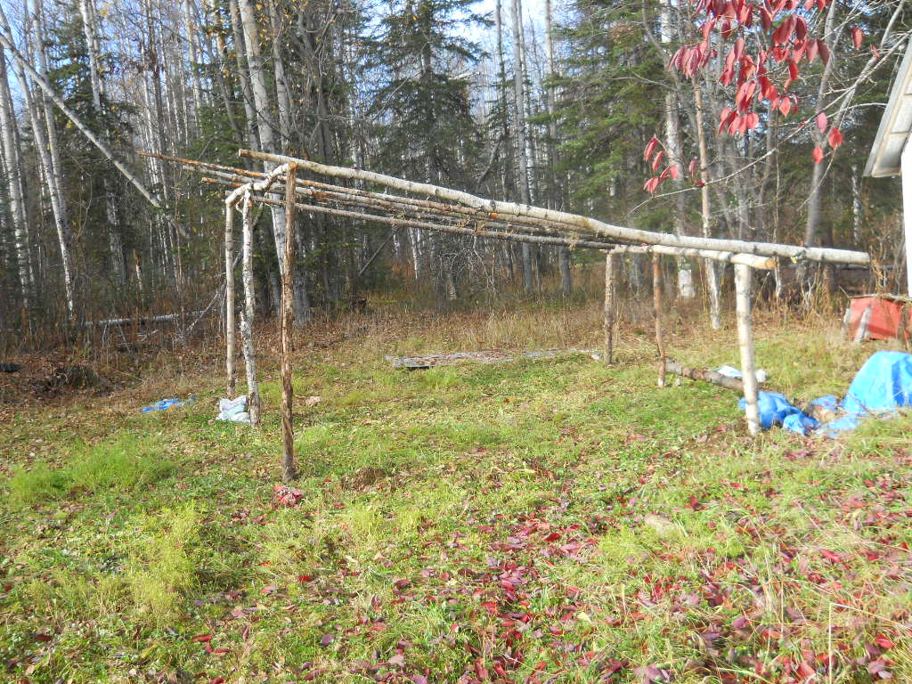
And here you can see our simple structure. 
Now for the ridgepole, all held in by steel stuff at all critical joints. 

Then it was time for the rafters, which I measured and worked out. Since our design was off, because we didn't use batter boards in the first place, I recalculated the rafters.  In the next pic, Fluffy passed up screws. She brilliantly discovered that since the screwdriver is magnetic, all she had to do was pass up the whole drill, screw and all, to John...
 ..who then could screw the rafters in. We used screws rather than nails; much stronger.
 At the end, we have a respectable snow splitter. We used salvaged roofing for, well, the roof.  It will divert the snow off the door! A lot of detail work left, like the flashing along the ridgepole. We'll do that, if only it stops raining.
 
Of course, this thing suggest YAP (Yet Another Project). Extend this thing all the way to the shop. Then we can walk to the shop in winter, unhindered by snow. So many projects, so little time.

Wednesday, October 3, 2012

Shaped planes, part VI (and counting) -- a plow plane

Once again, a plane-making chapter in this series. The ultimate object, of course, is to make picture frames in 14th century style. To make a frame you make a molding. Once you have the molding it is not so hard to make a frame. But to make the molding  you need molding planes, i.e shaped planes. After some experimentation I decided to make a plow plane. See the YouTube video I cited a good while back (Florentine 14th Century Frames). It is used to make the stair-steps (rabbets or rebates) that are later smoothed out to make the molding.

Of course, nowadays everyone uses power routers. But not me. In the old days it was all planes, and that is where I'm going. Onward!

Construction of a plow plane begins with the body. This is a priceless piece of oak, 145mm x 40mm x 22mm. It was once my daughter's dining room table, and the 22 mm is the thickness of the wood -- no doubt something in RGU, the Henry III units beloved by the USA. But oak does not grow in Alaska. I can live with 22 mm.  The first thing is to make the body.

I have constructed an oddly-shaped mortise and a plain old rebate, or rabbet, in the block of wood. The oddly shaped mortise slopes at 45 degrees and 60 degrees respectively. The 60 deg is arbitrary. It will acommodate the wedge. The 45 deg. is the bedding angle for the plane. Wedged planes are ancient. But they are very effective. Not quite as convenient as a screw adjustment. And why the rabbet? Well, the plow is a skated plane. The plane rides on a skate, or piece of steel. I have temporarily attached the skate to the rabbet in the body.

 The skate itself is made of a piece of steel from a worn-out  Japanese saw. I had to anneal it to drill the holes for attachment. Hence the lovely colors in the skate. No art, just necessity. The skate is two-piece. The leftmost provides support for the blade. It takes a bit of fussing and fiddling here to get the proper clearances for the front part of the skate. You want maybe 3mm clearance in front; have to allow cuttings to escape. When you have fussed and fiddled, you can attach the skate permanently.


 I have used an aluminum strip here, because I couldn't find brass of the proper thickness in Alaska. Note the brass rods sticking out of the side. They are for the fence. I'll do the fence later. The rods are in the wrong place, by the way. I had to move them later. That is not where they go! The rods themselves are welding rod 3mm thick. May be too flimsy. We shall see.

Next, we grind the cutter. I have gone into cutters before. I cut this one to shape on Gadget 1, see my last post. I had the good sense to make one of out of cardboard before I cut metal. It is shaped somehat like the letter L with a very thick horizontal. Final shape of the blade is obtained by grinding.  I did the bulk of it with a DTT (Dremel-type tool). The cutter itself is a piece of old circular saw blade. Then we use a wet grinder to put a preliminary edge on the thing. I have no picture of this, because in the middle of battle one often forgets to take pictures! No war correspondents here.
 
The next step is to add a fence.  The fence is a piece of wood that causes the plow to go at a fixed distance from the edge of your molding. It is attached to the brass rods I mentioned before (now relocated), with a pair of thumbscrews to keep the fence from creeping away and ruining your molding.
There is a lot of work still to be done, of course. I have to grind the cutter to its final shape, file the groove in the cutter that makes it ride on the skate, really sharpen the blade (see my thread on sharpening); in fact lots and lots of details and tuning. The piece of wood at the bottom of the picture is a stand-in for a molding blank. You can see that the plane will cut a groove in the blank. This is what we want, after all.

You can find plow planes in antique stores, at exorbitant prices. They are also made in Asia, not so exorbitantly priced. You can plunk down a great deal of money and buy the beautiful Veritas plow plane (search on plow plane). I refuse. It is much more fun to make my own. I remind you of George Dyson's (q.g.) saying, "never buy anything you can make, and never buy anything you can find."