Showing posts with label shaped planes. Show all posts

Wednesday, October 3, 2012

Shaped planes, part VI (and counting) -- a plow plane

Once again, a plane-making chapter in this series. The ultimate object, of course, is to make picture frames in 14th century style. To make a frame you make a molding. Once you have the molding it is not so hard to make a frame. But to make the molding  you need molding planes, i.e shaped planes. After some experimentation I decided to make a plow plane. See the YouTube video I cited a good while back (Florentine 14th Century Frames). It is used to make the stair-steps (rabbets or rebates) that are later smoothed out to make the molding.

Of course, nowadays everyone uses power routers. But not me. In the old days it was all planes, and that is where I'm going. Onward!

Construction of a plow plane begins with the body. This is a priceless piece of oak, 145mm x 40mm x 22mm. It was once my daughter's dining room table, and the 22 mm is the thickness of the wood -- no doubt something in RGU, the Henry III units beloved by the USA. But oak does not grow in Alaska. I can live with 22 mm.  The first thing is to make the body.

I have constructed an oddly-shaped mortise and a plain old rebate, or rabbet, in the block of wood. The oddly shaped mortise slopes at 45 degrees and 60 degrees respectively. The 60 deg is arbitrary. It will acommodate the wedge. The 45 deg. is the bedding angle for the plane. Wedged planes are ancient. But they are very effective. Not quite as convenient as a screw adjustment. And why the rabbet? Well, the plow is a skated plane. The plane rides on a skate, or piece of steel. I have temporarily attached the skate to the rabbet in the body.

 The skate itself is made of a piece of steel from a worn-out  Japanese saw. I had to anneal it to drill the holes for attachment. Hence the lovely colors in the skate. No art, just necessity. The skate is two-piece. The leftmost provides support for the blade. It takes a bit of fussing and fiddling here to get the proper clearances for the front part of the skate. You want maybe 3mm clearance in front; have to allow cuttings to escape. When you have fussed and fiddled, you can attach the skate permanently.


 I have used an aluminum strip here, because I couldn't find brass of the proper thickness in Alaska. Note the brass rods sticking out of the side. They are for the fence. I'll do the fence later. The rods are in the wrong place, by the way. I had to move them later. That is not where they go! The rods themselves are welding rod 3mm thick. May be too flimsy. We shall see.

Next, we grind the cutter. I have gone into cutters before. I cut this one to shape on Gadget 1, see my last post. I had the good sense to make one of out of cardboard before I cut metal. It is shaped somehat like the letter L with a very thick horizontal. Final shape of the blade is obtained by grinding.  I did the bulk of it with a DTT (Dremel-type tool). The cutter itself is a piece of old circular saw blade. Then we use a wet grinder to put a preliminary edge on the thing. I have no picture of this, because in the middle of battle one often forgets to take pictures! No war correspondents here.
 
The next step is to add a fence.  The fence is a piece of wood that causes the plow to go at a fixed distance from the edge of your molding. It is attached to the brass rods I mentioned before (now relocated), with a pair of thumbscrews to keep the fence from creeping away and ruining your molding.
There is a lot of work still to be done, of course. I have to grind the cutter to its final shape, file the groove in the cutter that makes it ride on the skate, really sharpen the blade (see my thread on sharpening); in fact lots and lots of details and tuning. The piece of wood at the bottom of the picture is a stand-in for a molding blank. You can see that the plane will cut a groove in the blank. This is what we want, after all.

You can find plow planes in antique stores, at exorbitant prices. They are also made in Asia, not so exorbitantly priced. You can plunk down a great deal of money and buy the beautiful Veritas plow plane (search on plow plane). I refuse. It is much more fun to make my own. I remind you of George Dyson's (q.g.) saying, "never buy anything you can make, and never buy anything you can find."


Thursday, September 27, 2012

Two gadgets

As you know, I have been making shaped planes and John has been melting aluminum (aluminium, for my British readers)  to make castings. Now both of these activities have groundwork to be done. In my case I make my own plane blades from scratch, namely scrap steel. I cut my blades from circular saw blades. In John's case, he cannot obtain very fine-grained sand without importing it from the lower 48 states, at enormous expense, so he sifts it by hand from what he can find. Both these activities have one thing in common. They involve extensive manual labor.

A circular saw blade is cheap. A used circular saw blade is free. It is very tough steel. It may even have carbide teeth, which cannot be cut (or sharpened) by anything short of a diamond cutter. I collect used circular saw blades. But they are difficult to cut with a hacksaw and the process finally got to me. So I built gadget one.
Long ago I acquired, at a thrift store, a used Makita hand-held circular saw. It had no blade guard, so it went really cheap. I used it on construction projects.  Now I really hate power tools, but this is an excellent one of its kind. So what I did was to put an abrasive cutoff blade on it (ACO).  This is much better than buying an angle grinder. I made a sort of tablesaw out of it. I bolted it to a piece of scrap "table" I had lying around. I am a wood scrounge.  The hardest part was bolting the thing to the table. Circular saws are not meant to be bolted to tables. The manufacturers want you to buy their tablesaws, which I consider an invention of the Devil. But with this gadget I can cut up a circular saw blade in minutes. I can use both hands on the work. I can use the sides of the blade as a rough-and-ready grinder. Mind you, I am no stranger to the hacksaw. But neither am I a 100% purist. Hand tools only? Well, there is a limit. Just try hacksawing a circular saw blade yourself. And of course the whole thing bolts to the faithful shop Workmate, the greatest British invention since the steam locomotive. I have it weighted down with about 50 Kilos of logs, so it isn't going to move easily. I can use both hand on the work. I can cut metal or even rough-grind it to size. Invaluable for making metal objects, such as plane blades.
 
 Gadget two is a bit more specialized. It is a power sand siever or sifter.  I did not invent it. I found the idea on  the myfordboy blog, on his YouTube channel, video #31. This is a blatant knock-off. My thanks to myfordboy. It is a power sifter based on a reciprocating saw, the kind called a sawz-all in the trade. No doubt a trademark. I picked this one up for about $10 at a yard sale; the trigger is very dicey. But it works.

The reciprocating saw drives an arm connected to the saw. Arm is connected to sieve. The cost, apart from the $10 reciprocating saw, is zero. It's all someone else's offcuts, plus some salvaged strapping steel as guides.  By the way, it is very difficult to drill holes in sawz-all blades. I had to use a drill press. Even then it was difficult. Also had to add weight to the thing. But the thing works. It sifts as fast as you can shovel the sand in.

 Note the duct tape, known as "gaffer tape" in the UK. Without this commodity, the state of Alaska would grind to a screeching halt. I do not remember the official motto of this state, but the unofficial motto is "if it moves and shouldn't: duct tape. If it doesen't move and should: WD-40." Oh, how true.

Saturday, September 8, 2012

Shaped planes, Part V: new guy on the block

I know, you may be tired of this shaped plane business. It has been quite an obsession. But the old hollower just did not work. I had to remake it and this time, as an experiment, I decided to try a pattern I found in David Finck's book, Making and Mastering Wooden planes, q.g. Great book. This is not a Krenov-style plane. It demands a different blade outline, as you will see. First we cut a triangular mortise in our block of wood, which we shape to the blade outline. In fact the outline was exactly the outline of my previous plane, which in turn shaped my rounder plane. The rounder works quite well. So I used it to shape the bottom. Easy. Five minute's work.

Lay out your plane. Draw lines on the wood. Layout is critical. I may put a post in on the subject. Then saw out the mortise down to the required depth. In my case 1cm. Then chisel out the waste. Do this very carefully.
For the record, the dimensions of the block are 140x21mm. Not responsible for the 21 mm dimension, no doubt some meaningful number in RGU. As you see, I have two ramps. The left one will be the called the blade ramp. Once cut it will never be touched. It is a 45 deg. angle with the sole of the plane. This is standard pitch for a plane. If you plan to cut hardwoods you might want a classic York pitch, 57 deg. The other one is the wedge ramp. I happened to cut this one at 60 deg. It is not critical. You will cut the wedge to suit it. My ramp is one cm deep; 10mm for the units nannies who keep insisting on obsoleting centi- and deci- prefixes. Fie! Computerization strikes again. If you can't multiply by ten in your head, you have real problems and should be back in first grade. And would never read this blog in the first place.

Next chore is to shape the blade. Critical. My blades are (so far) all of 10 mm radius. So I cut out a piece of circular saw to approximately the right shape. I must tell you how I do this, it is a nice journey all by itself. Draw your blade on paper. Cut it out oversize. It can be done with a hacksaw. A grinder is nice too. Do not worry about the radius too much at this point, but leave a generous (2mm at least) allowance. So what we have at this point is something like this.
Actually I made several mistakes. I did not cut enough oversize. No matter. Same old story; easy to take off, impossible to put on. One mm off. Fix later.
In order to aid fitting, you will have to make a cutout on the non-ramp side of the plane. When you do, cut on the wedge ramp side of the plane. Never touch the ramp! Lesson learned from the first plane.
It really helps if you have put the layout lines on both sides of the plane. I did not. Mistake. Lay the thing out completely on both sides! Learn from my mistakes.

Next step is to the blade to an exact circular radius with a 25 deg bevel. Very easy to grind the shank, for instance, down to 10mm flat. But grinding a circle with the proper radius is no joke. If your hand is steadier than mine you might do it. But at the same time you have to grind a 25 deg bevel on it. For superman? Child's play. For the rest of us it is time to cook up a jig. As you can see, the center of curvature is right at the corner of the shank. I filed up a small (ca. 1 mm) cutout there. As for the jig, here's v0.0...
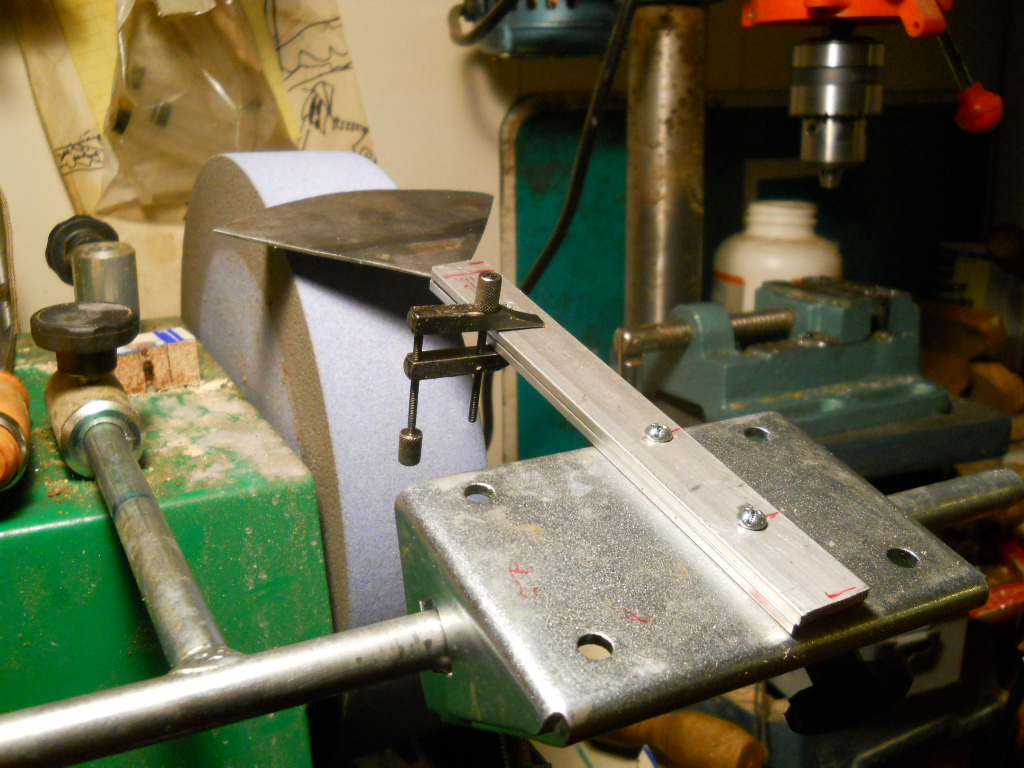
Lot of things going on here. The whole thing is done on my TSO (Tormek-Shaped Object) wet grinder. The bottom part of the jig comes from the kindly asiatic manufacturer. Let me call it the table. Bolted on to that is an aluminum bar, exact dimensions unimportant. About 10mm from the end of the bar, middle of the pic, is a finishing nail, about 0.7 mm nail. Again some RGU system. I drilled the hole undersize, pounded it in, and used superglue to make sure it stayed put. I later improved this jig to grind ulus, but this one will do for now. My angulometer is being used to set the 25 deg bevel angle. This is done by pulling out the table support, also supplied by the manufacturer, and by rotating the table around the support. Now the blade is free to rotate on the nail, and all you have to do is rotate the blade. The blade does tend to come off the nail. So you have to hold it on the nail by hand. By the way the grinder rotates away from me. If I turned it around I wouldn't have this problem! But I prefer grinders rotating away. This jig cries out for improvement, which is why I improved it later.

Now turn the grinder on and start rotating the blade. As you do, hold the blade firmly against the nail. In a wet grinder, things happen in slow motion. On a dry grinder you ruin your work in an instant. And rotate the blade! I repeat, rotate the blade. If you don't you will grind a flat spot on the blade.

An ulu, by the way, has exactly the same problem. Got to grind a circular profile with a given bevel angle. The ulu jig works very nicely and you don't have to worry about holding the blade against the nail. I drilled a hole as close as I could to the center of curvature.There are two bars this time and a clamp to hold them together, but the principle is the same. Next circular plane blade I build will allow for a 7mm hole to be drilled at the center of curvature. This is jig v0.2.

And of course, you must harden and heat-treat the blade. Microforging; propane torch work. See previous posts. And hone it!

Anyway we now have a nice circular blade. Now we have to fit it to the plane. We want a zero throat opening at this point. The reason for this is that it is much, much, easier to cut wood away than to put it back. Gradually, with a chisel, open out the wedge ramp until you have a 0.5 mm throat or even less. The narrower the throat the finer the cut. Do not under any circumstances touch the blade ramp. Your final touch is to drill a hole to allow the shavings to escape. Do this last.

My hole is 22 mm because I happen to have a 7/8" Forstner bit, which drills a beautiful hole. Anything around that size will do. Drill tangent to the wedge ramp plus a few mm. Make a wedge 1 cm wide to suit your ramps and Robert est votre oncle, as the French most certainly do not say.

Plane works very well indeed. All wedged planes need extensive fiddling until you get the blade depth just right. Tap with a hammer. See Finck's book. Very pleased with this effort. I went to all this length because I have not found any source (besides Finck) who makes planes with shaped blades. Phew! Long post.


.


Saturday, September 1, 2012

Shaped planes, part V

My previous expenience with moldings disclosed that my hollower is not satisfactory. The plane chatters. This may be due to saveral reasons. The most likely is that the plane blade s not thick enough. So, sucker for punishment that I am, I decided to make a thicker blade. Double sucker that I am, I decided to use a different style, based on a picture in David Fink's book, Making and Mastering Wooden Planes (q.g.). Glad I did. I have learned a lot.

This style of plane is a lot more like the traditional wooden shaped planes.
Here you can see the overall scheme. We have a block of wood 145mm by 20mm thick by about 50mm wide. The bottom of the plane has been shaped to a 10mm radius curve, by guess and by gosh. In the block a mortise has been cut. Into this mortise will fit a blade. The blade for now is just roughed out. The mortise has two angles. The one on the left is critical. It is the bedding angle for the plane. The traditional angle for bedding is 45 deg and this is what I use, standard pitch. However for hardwoods you might want to use a steeper angle, like 57 deg which as I recall is called York pitch. These are traditional pitches, and assume the blade of the plane will be sharpened at 25 deg. If you do not sharpen the blade at that angle you will have some math to do. It is all about angle of attack. I recommend reading Garret Hack's The Plane Book, q.g.

It took me some time and a few trips to the 'net to figure out what the plane blade looked like. Mr Fink did not tell me. But eventually I figured it out. The roughed-out blade is shown on top of the plane. I cut it out from a piece of worn-out circular saw blade. This is almost 2mm thick. Approximately twice as thick as the old ripsaw-derived blade on my previous incarnation. I like this a lot. The thicker the blade the less the chatter.

The place where the blade goes in a not-so simple mortise. Leftmost is the ramp where the blade will go. I will call this the blade ramp. It is 45 deg, the bedding angle. If you go make one of these things, under no circumstances can you touch this blade ramp! At right is another ramp. It is traditional to cut this at 62 deg but I cut it at 60. Easier, (with a 30-60-90 square), to lay out and the exact angle does not matter; cut your wedge to suit. This ramp has two functions. One, it holds a wedge to keep the blade in place. So I will call it the wedge ramp. Two, you can see I can slide my 30-60-90 square along the plane towards the front (right in the pic) any amount I want. The amount I slide it towars the front will determine the throat opening. Planes are very fussy about throat openings. My rulae of thumb is that the throat opening should be about the width of the shaving you want to take. So my current strategy is as follows. The wedge ramp should be the thickness of the blade ahead of the place where the blade ramp comes out. The goal is for a zero throat width. I can take wood off. I can only put it back with great difficulty. In fact, only with Plastic Wood (tm).

So when we have fiddled with this a bit, we can get a decent fit.
A decent fit to me means that the blade will fit exactly flush with the bottom of the plane with zero overhang. So the throat opening is zero. That is what I want. To get away with this we have to look at the other side of the plane.
There is a blade-ramp shaped cutout on the other side of the plane. It hasto be deep enough to take the plane blade all the way down, until it is flush with the bottom. Took some doing.

My next post, part VI I suppose, on the subject will tell you about my adventures in throat-cutting. Fortunately, human life is safe. The only throat I intend to cut is that on the hollower plane. I must also relate my learnings on ramp-cutting. And there is yet the chip-escape hole to drill. So much to post, so little time.


Tuesday, August 28, 2012

Shaped planes, Part IV

After I did my last post, I reflected that the video I recommended goes by at warp factor five. Very fast. So I have decided to go step by step. This is my second practice molding. So we start with a scrap piece of wood left over from John's projects. We clamp it in the vise, and draw a picture on the end of the sort of molding we want. I have made this one up from scratch, but it sort of resembles the molding I cut in the previous post.
Now before you do anything else, flip the piece over in the vise and in the bottom of the piece, cut a rabbet. The purpose of the rabbet is to hold your painting. Here I am using the micro Veritas rabbet plane to do so. It cuts about a 6mm rabbet. About right. I have clamped a steel ruler onto the scrap piece of wood, AKA "stock" to guide the rabbet plane. If you don't do this your plane will wander. You will be upset. You will ruin your piece. Something thicker than a steel ruler would be better, because it will force you to hold the plane square to the work. I will call the tiny plane Peanut in what follows. When you plane a rabbet this small you spend as much time clearing shavings as you do planing. They clog up the tiny hole in the plane. But you do it. Now flip the piece over.
You can see the rabbet or rebate you have just cut, underneath at left. Now what we want to do is rough out the profile with rabbet planes. A rabbet plane cuts far faster than a shaped plane. A plow plane would cut even better. But this piece is about 20 cm long and the plow will not track properly. If I can, I use Big Daddy. This is the macro sized Veritas rabbet plane. He cuts big time. A joy to use. And he does not clog up.
Now, what are we trying to do? We have a continous curve in the profile. We obviously have to remove some wood to get there. Differing amounts of wood, depending on where you are in the profile. So we are trying to approximate the curve by staircase steps. Engineers call this a step function approximation. So I cut rabbets, guided by fences, until I come to the point where I cannot clamp the fence any more -- too irregular a profile. Forget about cutting rabbets freehand. Superman can do it. Most of us can't. At this point our molding looks like this:

I cheated a bit and used a flat plane (violin maker's plane in fact) to get a slope in the part to the right. But you can see the stair steps. Now we are ready to hollow out the big curve at the right. Break out your hollower.
Now plane out the hollow. Do not be too fanatic about your drawn profile. Your hollower has a fixed radius (10mm in my case) and your eyeball had another. Look at the thing. Does it look okay? Stop. Do not be afraid to hold the hollower at an angle, as I am doing in the above pic. Sometimes it cuts better that way. I have a lot to learn still. The rabbets you cut guided the hollower. Superman excepted, you need a guide for a shaped plane; the rabbet (or groove) provides it. So you cut straight and do not wander.

We have dug a lovely curved trench in our profile. Here it is:

It does not quite match the drawn profile. Of course it doesen't! One drew the profile by eye. The hollower has a fixed 10 mm radius. Miracle if they matched. Do not be concerned too much by this mismatch. It still looks nice and that's what matters. Now let's do something about the hills, having done the valleys. We break out the rounder plane. This has exactly the opposite curvature as the hollowers. All I have at this point is 10mm radius. The rounder looks identical to the hollower. (except for the bottom). It is a bear to sharpen. After I applied it I had something like this.

Needs some more work but is recognizable as a molding or picture frame. It was at this point that I realized that this business is just like carving. You are limited in carving by the sweep of your gouges, i.e. curvature. You are limited in in moldings by the radius of your plane. Sigh. It looks like I am into a whole new era of plane-making. Need some much narrower radiuses, say 5mm. To start. If I were in 14th century Florence I would have gone to Giuseppe the plane-maker and ordered up a bunch of radii. The bill, no doubt, would have been paid by Cosimo de Medici, who wanted some frames for his pictures. But here I am in Alaska, got to do the whole megilla myself. Cosimo de Medici nowhere in sight.

I did a bit of cheating and applied a violin-maker's plane (commercial) to the thing and got a perfectly decent molding. We are not there yet, but we make progress.

Thursday, August 16, 2012

Plane and fancy

This is a long overdue post. It begins with the fact that I got all wound up over carving after reading Chris Pye's book, Wood Carving, which you may google. Then this morphed into a project of John's, namely making custom picture frames for his paintings. My job is making the frame. Now you may go to the Home Despot and buy commercial moldings and make your frames out of that if you wish. But I soon realized that I would have to make the moldings myself. And I refuse to use a router. So it's back to basics. Let us build shaped planes and use them to shape the moldings on which we will do carvings, out of which we will build frames! Really unwinding the Industrial Revolution.

Back in the pre-router days, people used planes to make moldings. They had all kinds of elaborate shapes. I wanted to start simply. So I decided to make a hollow and a round. One cuts a hollow, the other makes a round out of a raised piece. Now I have made some miniature planes but this is real stuff. Tough. First, you have to make a blade. The blade is the crucial part of the plane. I used an old rusty crosscut saw for the purpose. In retrospect it was much too flimsy. But hindsight is wonderful.

I started out with the rounder. This is a concave blade, an upside-down U.
First problem is to find your raw material. Maybe a circular saw blade. I used a handsaw blade, but I think a circualr saw blade would be better. I cut it roughly to shape, with a hacksaw, and I started out with full metalworking equipment, the milling attachment on the Taig. At least I got the bottom of the thing milled out flat.
But there was no way I could cut a semicircle with the mill. I do not have a rotary table! Nor yet a cutter of exactly the proper radius. So, when you have to cut shapes out of metal, you resort to drilling:
Since I am drilling a semicircle, I stuck a steel pin in the backing board at the proper radius. It fits into a hole in the proper point of the proto-blade. This, at least, ensures you are drilling on the radius of a circle. Do not move the backing board. Clamp it, preferably. You are trying to drill overlapping holes. Then cut off any webs and clean it up with files. At this point I decided to give it a preliminary grind, as I usually do with my hand-made tools.
Terrible mistake. You should not use a flat grinder to sharpen a curved tool. I do not know how Tormek & Co. do this, but their grinder just ground me flat! I ruined the blade.

So I took a deep breath, said some unseemly things in several languages, and decided to make a hollowing plane instead. U-shaped. The iron for this was made exactly the same way as the previous one, but when it came time to grind, I rotated the blade. I made a jig for the purpose. I also use the jig to sharpen gouges. Don't have a picture of this (yet) but it's just like sharpening a gouge, only the blade is flat. At last a nice edge. So I hardened and tempered. I will soon post something on this. And I had a semicircular plane iron, only shaped U instead of upside-down U.

So now we have to make a body for the plane. We are making the Krenov plane style. It is a laminated thing, you saw off the middle and glue it back again. I have been here before and will not repeat it. But here are the pieces of the plane.
Here we have the iron, the sawn-put cheeks, and the middle part, sized to take the iron. We have simply drilled a hole to let the chips escape. The middle part is shaped for a wedge, to hold the iron in. For the record the dimensions are 145 x 50 x 23 mm. The 23 mm is a curious number, it must be something in inches, but I don't do inches.

Observant readers will note a terrible mistake. I did not drill registration pin holes when I sawed it apart. I paid very dearly for this mistake. Almost as bad was the fact that I did not draw layout lines on the outside of the body. When it came time to cut the throat opening of the plane, I cut my own throat. So put down layout lines on the outside -- it saves infinite trouble. You must cut the throat at the smae angle as the bedding angle (45 deg) . In the end (OK, confession is good for the soul) I used plastic wood to remedy my mistakes. Here half a millimeter is crucial. No big deal to cut the throat; but cutting at the proper angle is another matter. You want a very, veye, narrow throat on these things. It has to shave, and the throat opening roughly equals the thickness of the shaving you will take.

Now on to the rounder. I cut a block of wood exactly like the previous one. I remade the blade. It is still in a rough stage. But the curvature is right. Exactly the same radius as the hollow. So now we can use the hollow to shape the rounder.

Note the plastic wood infill on the hollow. But it works. It planes. It is not as smooth as I would wish. I need a fence to keep the hollow straight. It needs a thicker iron. But it planed down the sole of the hollow.

I used a circular rasp at the end, and sandpaper wrapped around a piece of pipe at the end. But the rounder has a nice shape. A few flaws. They are correctable. This time I remembered to drill registration holes. Oh yes, andI have sawed the back end of the hollower to a curve. Else it digs into your hand. Live & learn.

It is time to saw the thing apart. I can hardly wait to make an ogee, q.g. If circles cause all this much toil, I wonder how I will do the ogee. Stay tuned.