Showing posts with label Wooden Clock. Show all posts

Monday, August 19, 2013

The pendulum swings

It has been raining cats and dogs. Or in Spanish, always more colorful, palos de escoba  y capuchinos de bronce. Brooomsticks and bronze capuchins. I assume capuchin Friars made out of bronze are extremely heavy. So with the rains. So since I can't go out and weed without getting soaked I have been doing some clock  stuff.

This time we will make a pendulum. The pendulum is an antique device. Galileo was the first person to document its workings, but it must have been known before that, because Galileo, smart as he was, did not invent it and never claimed he did. However, he did scope it out. He worked out the basic pendulum formula, which you can find anywhere and I will not repeat it. It is a curious fact that a pendulum with a one meter length will do a beat (the "tick" of "tick-tock") in one second. Almost. When the Frenchmen of the 18th century invented the so-called metric system (it should properly be called the decimal metric system) they considered using the length of a pendulum that beat one second as the length standard. They wisely rejected this, because they realized their time-keeping devices were crude. Instead they took a ten millionth of the Earth quarter-meridian as a length unit, AKA meter, and proceeded to measure out the length of the meridian -- a monumental undertaking by any standard. Especially during the Revolution, when surveyors were regarded as spies.

But we digress. Let us make a pendulum for the clock. We are fortunate that the major part of this is simply a commercial three-foot dowel from Lowe's. But a pendulum needs a bob. This is a heavy piece on the end of the dowel. I was fortunate to secure an offcut from one of John's projects, a piece of oak, intended as a stair riser. After a lot of staring at the drawings I finally figured it out (I think) and decided I needed a circle 80mm in diameter. So I got an offcut, marked out 80mm with dividers, and roughed it out on the bandsaw. Now we have to get it circular. This is lathe work, of course. You will soon find that if you need A you firt have to make B. In this case B turned out to be an arbor (lathespeak and not clockspeak) to hold the piece you need to machine. This took me an afternoon, but I do not feel bad about it because (a) I have an arbor for the future and (b) I learned a lot. I used a piece of very nice steel rod, taken from a defunct printer, to make the arbor. So let's put it on the lathe.
 The Taig lathe will "swing" a maximum of about 110 mm -- that is the center height is 55mm  or so(actually 2.25"). It is an RGU lathe. The bob is very close to the limit of the lathe. Wood or no. It is not only the swing, it is getting the tool to work. It took quite a lot of maneuvering with angles, tools, and general fussing around to get it down to where I wanted it, 80 mm diameter.

 At the end, we turned the thing. It remained to drill a hole 1/4" through it. This was a major undertaking. A "jobber's length" 1/4" drill can do the job. Barely. My drill press can drill 50 mm , but it is outclassed  by the 80 mm diameter. I finished it up with a cordless. And no drill goes straight, nor round.  More about this some other time.

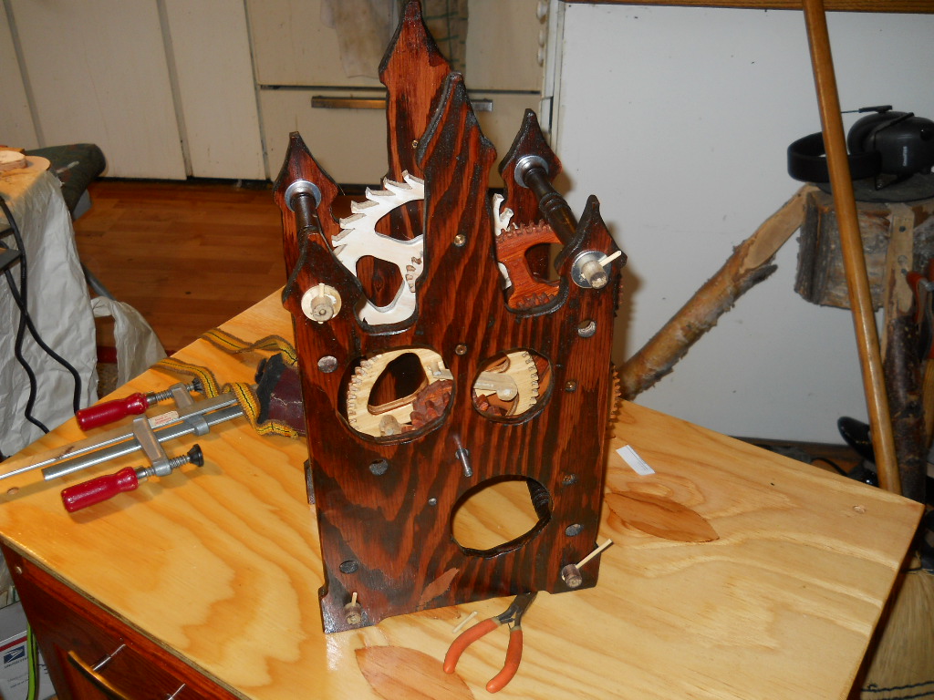
So here's the pendulum:


The pivot is the circle on top. Then the 3' (about 94cm) rod, then a sleeve, and then a piece of hardware store threaded rod, below of which sits our bob. I will have to make up a stand, because as you can see, the pendulum is too long to clear the cart which John built for me. It's a few cm, that's all. Not too bad for a couple of rainy days. The reason for the threaded rod is rating. By adjusting the nut at the bottom of the whole thing you can adjust the beat to accomodate friction, weather, and other misfortunes.

Thursday, August 8, 2013

Clocking the clock

This year the mosquitoes have been worse than I have ever seen. I have a head net. This is how I have been able to work in the garden, walk, ride my bike, and do a few other things. But it has also started to rain. Good for the garden. Bad for outdoor work. The long and the short of it is that I have some indoors time. I have spent it on the Wood Clock. You will recall that we had gotten it to its semifinal state, but time out was taken to finish the wood. So one rainy (or mosquito-y) day I put the thing together again.

Alas, it was jammed up tighter than the proverbial drum. It really looks pretty, though. Problem is, the finishing process destroyed -- or at least seriously interfered -- with the fit of the teeth. So begins the ordeal of refitting. First thing I did was to put a dial test indicator on the wheels. This gadget is cheap and amazingly accurate -- it can be read to .0001" ( thou) or .01 mm, one "cent". It took some doing. First I had to clamp the clock to the table. Actually to the super-cart that John made for me. It is fantastic. For this I used Jorgensen screws -- wooden clamps -- on the clock itself. Then I clamped a found piece of steel to the bench. That gave the magnetic base of the indicator something to latch onto. The British call the indicator a "clock" because it looks like a clock, so I was literally clocking the clock! Americans say "dialing the clock." Same thing. I like "clock" myself.
 

With  the "clock" I found  the wheel diameters varied between +40 and -40 thou (sorry, it's an Imperial Indicator) and that's a bit too much. Lots of reasons for this. One is that the shafts, or arbors, might have warped. Another is that the humidity is much higher. Another is that the arbors are probably off center. A real menace, but a drill bit drills neither round nor to size, and this causes wobble. Lastly, the plates themselves may have warped a bit.On the other hand the pinions were plus or minus 0.010" which seemed quite respectable. I went for the wheels, since they seemed to be the main culprits.

So I went wheel/pinion pair by pair and got them to spin freely again. This is a tedious task indeed. You have to sand until everything spins. On the third wheel I had to cut the teeth deeper, and I used the invaluable Dremel for the purpose. I did say it was tedious and I do not think it redundant to say again that it was tedious.

However, at the end...

...the clock is together again. Note that the finish is gone from all the teeth. It spins freely. Any binding would stop your clock. Mr Wilding's ideas on pivots are very good. But the adjustment is critical. What we have is little pointy things (pivots) running in brass bushings, and this is a Good Idea. But if the pivots are so much as 0.1mm too short they fall out of the bushings. If they are too long they bind. The pivots must have some slop, called endshake in clockspeak. About one mm. If this is not provided, once again the clock binds. The clock has to rattle a bit. In brass this is no problem; but wood is a cantakerous material.

All the wooden clocks I have seen on the You Tube videos use steel arbors (shafts) and I think this is a much better idea than wooden shafts, even with the steel pivots. Steel does not warp as much as wood. But I followed the original plans and the book, and I learned something!

Meanwhile, I notice that nobody, myself included, can resist spinning the clock as they walk by. It is a Zen contraption.

Tuesday, May 14, 2013

Creeping up on a new clock

First of all you should be aware that the wooden clock is alive and well. It is being finished at John's cabable hands. There are a whole bunch of fiddly parts that have to be finished.And there is still the pendulum, and the weight, and the pulleys. Lots of stuff to do. The backbreaking work is over, though.

But until they are finished, I can't work on anything else. So, as I have said before, I am jump-starting my next clock. This is the Isaacs clock.

The real problem with making clocks is making the wheels, i.e. gears. The real problem with making wheels is the wheel cutters. So since my last post I have been obsessed with making cutters, I am following a page which I supplied before, so I will not bore you with the details. I will say that it has been quite difficult. Now you could order these cutters form Mssrs. P.P Thornton in the UK for a modest 40 UKP apiece. Gulp. No. I must make my own cutters.

The cutters in question are described in Dean's pages, which I linked before. THe trouble is actually cutting them. Of course, I am not using "1/8 tool steel" as Dean suggests, because this is Unobtanium in Alaska. So I am using an old lawnmower blade. Very tough stuff.  It resists even my carbide tools. Plus it is an interrupted cut. The lathe tool cuts only sometimes. Since it it made on an eccentric arbor, that is, the center of rotation does not coincide with the center of the tool, it is very difficult even with carbide tools, which is what I am using. I persevered. I learned. Next time I will use my newly acquired angle grinder to rough the thing out. These things are at the extreme limit of the Taig lathe.

In the meantime, I read, on a clockmaking forum, of the equipment of some fellow clockmackers. This included a gentleman with an 18" South Bend lathe. That's about 450 mm swing and would have breezed through the cuts that strained my 55 mm lathe. Wish I had an 18" South Bend. "I like to take big cuts," said the owner.

But eventually, about a week or so later, I wound up with a cutter blank.
This image is a little confusing. There are four holes filled in with JB-weld. They don't count. The ones that do count are really half-holes. Notice the shape of this thing. It is a sort of a square with rounded sides. That is the effect of the eccentric arbor. The rounded sides provide relief.  See Dean's page, previously cited. It took forever to get to this point.

However, we got there. The next stage is to make a form tool to shape the cutter teeth.

This whole thing is unwinding the Industrial Revolution. You need A. But to make A you need to make B. But to make B, you need to make C... and so on.  Either that, or pay Mssrs. P. P Thornton Ltd. forty quid for one cutter. Ouch. I will make my own, and and a very interesting experience, too. A fine fate for a recycled lawnmower blade.

Wednesday, April 17, 2013

Finishing a clock (literally)

The time has come, the walrus said, to speak of many things (Lewis Carrol, The Walrus and the Carpenter). And now we have to put on a spurt of effort and actually finish the thing. Literally. Among the major projects done since my last post, the biggest is the minute work. Clockspeak, of course. In my case this is a misnomer. The Center Wheel revolves at a majestic rate of one revolution per hour. Great thing for a minute hand! But, as you will immediately see, this is not really cool for the hour hand. In one hour, given our 12-hour dials, the hour hand has to go round 1/12 the distance. (12 hours in one half-day). So what to we do? Add more gears, of course. Now I had cut these gears on the bandsaw long ago. But now we have to depth the wheels and pinions.  Clockspeak rears its ugly head again. Remember, big gear is a wheel, small gear is a pinion. Depthing means make them run freely. Book recommends sandpaper. I found a better way. Mr Wilding didn't know about Dremel tools or he would have done this himself. Book published in 2002 or so.
 So I did something I should have done long ago. Live and learn. I measured the aperture between gear teeth, and it is close to or exactly 3mm. I searched my inventory of Dremel tool accessories and found a router bit very close to 3mm. I put the wheel into the Taig and the Dremel into my vertical milling attachment. With this setup I could shave 0.01 mm off the teeth, and shave them I did, running the Dremel at max. Saved hours of work. I used my 60-hole dividing head to position (index) the teeth. Forget sandpaper. It was very nice that these things are 30-tooth gears; my 60-hole dividing plate can handle them easily. Pinions done same way; again they fit my 60-hole dividing plate.

This bit done, the we are almost through the major work on the clock. So the big moment has arrived. The clock was taken apart. If you make a clock, you will soon learn that the fate of a clock is to be taken apart. I handed the clock over to John. He is to make it look pretty. He is very, very, good at that.

 Gulp. The paper patterns have been sanded off. I feel lost without my paper patterns. But go they must. So John got rid of them. My only spec was that the various wheels should have different colors. Here, John is staining the Center Wheel. Previously he has sanded it. Gone is the paper. Again, gulp.
 The plates look very nice in a much darker color. They have a certain character.
There are many details with which we have to deal. But amazing.  A piece of very cheap plywood turns out a very nice clock.

Endless details. I have to smooth out the escape wheel. I have to make the pendulum...  never mind. Progress is progress.

While all this is going on I am setting up to make my next clock. It will not be a wooden clock. And that is all I will say at this point. But clockmaking is not a hobby. It is an obsession.

Wednesday, April 3, 2013

Clock: escaping from reality

If all there were to a clock (wooden or otherwise) were a bunch of gears with a weight (or spring) attached, then it is probably pretty obvious that the falling weight would just unwind the gear train at the proper rate for whatever weight you put on it. Minus friction. So how does a clock keep time? It has to have an escape mechanism, clockspeak for a device that interrupts the weight on its Newton-ordained fall to the ground. The escape mechanism on a clock is usually, in a clock, based on a pendulum; since a pendulum of a given length gives you a very steady beat. But alas, there is friction. You can easily make a pendulum. Put a weight on the end of a rod. Put it in some sort of pivot. A nail, say. Push it. You will see that eventually the pendulum beats no more. Friction, you see. So there is another function the escape mechanism must perform. It has to give a bit of a kick to the pendulum, to counter-act the evil friction. Actually, friction can be a Good Thing (TM) else your car wouldn't stop when you hit the brakes, but in clocks we really, really, don't like it. Again in clockspeak, the bit of a kick is called impulsing the pendulum. Over the years, nay centuries, there have been numerous very clever humans who have designed escape mechanisms, as a Google search on "clock escape mechanisms" will convince you. Mine is what the designers of this clock deemed best, a "deadbeat escape mechanism". There are many others.
The basic escape mechanism consists of the anchor and the pallets.The anchor consists of a piece of wood. You can see the anchor very clearly in the pic above. It looks like an anchor! The pallets are pieces of brass. Resist wear, you see. It was fun making the pallets. I milled them on the lathe, but took no pictures because it was a very simple job. Then I filed to the required angles. Now I have to adjust them, but that will take time (it's a clock!) and I have postponed it. I moved on to that tedious job, the minute work as it is called. The thing is, the clock is set up (all those gears!) so the Center Wheel (one of the gears) revolves at 1/60 times a second, or in other words one minute. But there is an hour hand. It must go around the dial much slower than the minute hand. In fact it must go around 60 times slower. (assuming you have a 12-hour dial). More gears. That's what the minute work is for. Another gearbox. Now the wheels were cut out on a bandsaw by hand. Hardly precision work. Furthermore here are small imperfections caused by the fact that you did not drill the holes for the axles, or arbors, exactly where you should. So we have to depth the gears (wheels). In this clock, says Mr Wilding, this involves sanding off bits from the teeth until the gears spin freely. At first I tried sandpaper. Very slow. I spent three days depthing the wheels. Then I got smart. I rigged up my lathe with it Dremel milling jig, which I described elsewhere.


The Dremel has a router bit in it. With this baby I can take off as little as .01 cm (or .0005") at  one go from the wheel. (Not really. This is wood, not metal. Precision is futile). This speeded up the problem considerably. Couldn't have done this with the going train (the main gears) because the wheels are too big to "swing" on my little Taig. Later I got even smarter. But that's another post. Live and learn.


Friday, March 15, 2013

Clockwork

I am back to clockmaking. I have been running into problems. Mr John Wilding wrote the instructions. But the drawings that come with the instructions do not reflect the modifications. Mr Wilding, as I have said, has built more clocks than I have passed power poles. He modified the pivots. Engineers call these things "bearings". He used pointy steel ends for his axles, which in clockspeak are called arbors. These pointy things run in brass tubes pressed into the clock frame, or plates. . We made the plates in episode 0 of this saga. So I have to make the arbors first, drill them for the pointy ends (called pivots in clockspeak, got that? Even in Italian they are called pivots) and then make the brass tubes, called bushings and this is engineerspeak too, so I can deal with it. Unfortunately the drawings (plans if you prefer) do not reflect his mods. Mr Wilding's mods are really very good; they cut down on friction, the deadly enemy of accuracy on any clock, wooden or otherwise.


 I first made the "center wheel" arbor as it is called. It calls for a 12mm dowel and (actually 1/2") and I had no such animal. So I turned down a 3/4" dowel. This was a Good Idea (TM). No commercial dowel is either circular or straight. It is not even dimensionally correct. Above, I am center-drilling the arbor to put a pointy thing (pivot) through it. Now this is no mean feat on the Taig lathe. You must support the outboard end so that the arbor does not whip about. I used my home-built steady-rest, mentioned elsewhere. This required boring out the center hole on the steady-rest to 12 mm + which was a project all by itself.

Finally I had the hole drilled. Now for the pointy thing (pivot) itself. This is a piece of steel hardware store rod with a 60 degree point on it.
 This was a breeze. I have finally learned how to turn points on things. I still have to work on my finish. I suspect my carbide tools are finally wearing out.  I am supporting my pivot on a collet. I have but the standard set of collets for the Taig lathe. But when you can use then they are marvellous. No runout (off-center) at all, unlike a standard chuck. Plus they will not take your fingers off, unlike the standard Taig chucks.

This pivot goes into the bushing -- or as Mr Wilding calls it, a bush. So we have to turn a bush from brass. This involves (1) cutting the thing, with a hacksaw, from my priceless stock of brass that I found at Fastnall in Anchorage, (2) drilling it through, (3) cutting a taper same as the pivot and (4) cutting to length.

Above I am at the stage of cutting the 60 degree taper on the bushing. I am using a priceless 60 deg. countersink picked up at Lowe's. 'Twill do. The other end of the arbor is a plain old piece of steel. Hardware store! I gave it a skim on the lathe to true it up. When all this is done, we can shove the wheel onto the shaft. This particular wheel has no pinions attached, a blessing. It will drive the minute hand.

So there we are. In the meantime we have have had lots of fun (and a great deal of trouble) making the arbors for the gear train that gets you from the escape wheel to this particular wheel. But the clock is beginning to take shape.

I am not in the least ashamed of my efforts so far. As the British say, the Words of my tune do not match the Music. Mr Wilding's variations on the clock (all for the good) do not match his drawings. And so I have to stop and figure things out. Worse, Mr Wilding uses RGU all the time. I refuse to work in RGU so I have to stop and convert, almost all the time. Then I have to deal with the RGU feed on the Taig lathe, but that is simple;  at least it's decimal and not absurd fractions of an inch. Next episode will detail (I hope) the rest of the "going train" which is clockspeak for the gearing that gets you from the pendulum beat to the hands on the clock.


Friday, March 1, 2013

The depth of the wheel (and pinion)

Today I finished the last wheel and pinion set in what clockspeak calls the "going train." This is the gearbox that gives you the proper relationship between the beat of the pendulum and (for example) the second hand. It takes three wheel and pinion (big and little gears) to get away with this.  It might take more if your clock has an oddball pendulum. Traditionally we have the "great wheel" which in turn connects via pinion to the to the "center wheel" and so via pinion again to the "third wheel" and so up to the "escape wheel." These terms date from the 16th century or so. When you start reading clockmaking books, or even looking at the internet, the terms reoccur over and over. By constant reading these terms are second nature to me by now, but it sure wasn't so at the outset.

But one problem at a time. Today's problem is "depthing."  More clockspeak. That is you have to put the axles, which are called arbors, so that the gears mesh correctly. Not exactly CNC. They did this easily in the 16th century! In a wooden clock, the technique is different. The holes are specified the by the paper patterns. The gears, as they come off the bandsaw, are guaranteed not to mesh. We are talking of tolerances of less than 0.5 mm. I defy anyone, Superman excepted, to cut something on a bandsaw to within 0.5 mm. That is the width of a thin pencil lead. So the teeth jam. So you have to sand them down so that they do mesh properly.

There are many reasons gear teeth jam. But a really big one is that the teeth are not the same length.  So today, finally learning from experience, I built a jig to get the same length on all the teeth of my last wheel/pinion combo. I thank the collective Internet for this idea. I am not the first person to build a wooden clock.
Above is the jig. It is a piece of wood with a finishing nail driven through it. It is clamped to my table. It bears against a circular sanding disk that came with my $10 jigsaw. You rotate the wheel (or pinion) and eventually it will sand the wheels down so that the teeth are exactly (well, maybe 0.05mm) the same length. In a brass wheel clock, you turn it on a lathe until the wheels are at the final diameter. Much easier. Well, we have chosen a wooden clock as our first effort. So we must deal with it.

Amazingly when I tried this wheel/pinion combo there was only one tight spot. Another reason your wheel/pinion combo sticks is that the teeth are too fat. A bit of work with a fingernail file and she was done. I am now ready to try the arbor-making business. The arbors, or arbours if you prefer the traditional spelling, or even asses in Italian or ejes in Spanish, are the axles on which the gears all turn.

Clockmaking is an obsessive business. I must be obsessive. I am enjoying  it.  The first combo took me four days, or maybe even five. The next set went in three days. This one went in an hour.

The moral of the story is that if you can see a pen line on the pattern, you have not sanded enough!

Sunday, February 24, 2013

Depthing the wheels

Once you have cut out your wheels (big gears) and pinions (little gears) the next step is to "depth" the wheels. This is clockmacker-speak for "getting the gears to mesh correctly." As cut and sanded, the wheels and pinions will almost certainly not mesh. Small errors in cutting the gears will magnify.

Now in a clock we have a huge gear reduction, possibly 3600 to one (that is the number of seconds in an hour). This huge reduction is accomplished in stages and that's why we have pinions and wheels. That is why a clock looks so complicated. Every wheel (lots of teeth) meshes with a much smaller pinion (few teeth). And we are dealing with wood, which even in its plywood incarnation is kind of recalcitrant. A clock put together in winter might not run in the summer because the change in humidity swells up the wood and the teeth jam. Brass is much more humidity-resistant and that's why we usually make wheels out of brass. We also make pinions out of steel.

But I am stuck with wood. I am not complaining! I chose the way myself. Now we have to live with it. Each wheel has a mating pinion. I'm following Mr Wilding's instructions and he as built an infinite number of clocks compared to me; this is my first clock. Anyway what Mr Wilding recommends I do.

So above I have very, very carefully drilled holes in the back "plate" (frame piece of the clock). The holes are just large enough to accomodate a finishing nail. I have cut off the head of the nail. And so begins a tedious odyssey. You spin say the pinion, the little gear at the top. At some point it will certainly jam. You look at it with a magnifying glass. If necessary with a jeweler's loupe. You determine what is wrong. In general if you can see ink lines in the gears it will jam. You carefully sand away these lines. It still may jam. You sand away some more. I use my swiss files and lady's fingernail abrasives, AKA nail files, very cheap. Let us be thankful for lady's long fingernails. So there we have one pair of wheel-pinions complete.

Very tedious. But watchmakers have the same problems, only at a much smaller scale. So I am grateful. I only have to  use a loupe occasionaly. I have a really nasty problem on the second wheel-pinion combo. Stay, as they say, tuned.


Friday, February 15, 2013

Sanding wheels on the clock

I continue my last post. Too tired last night to finish it. You will recall that I have to sand the wheels. So there are points where the linisher fails. I decided to make special blades for my Dremel jigsaw. It is an actual Dremel, by the way, and no knockoff; I bought it at the thrift store for $10. The problem with this jigsaw is that it uses pinned blades -- blades that have a cross-pin drilled through them. It will not accept ordinary scrollsaw blades. So we must overcome this. I cut a broken bandsaw blade into suitably sized pieces, and "blued" the ends. That is I stuck them into a propane torch flame until they turned blue. This softens them up so you can drill them.


Once you have drilled them you can silver-solder a pin into them. The pin was supplied by a cut-up safety pin. More than one use for a safety pin. Above we have the Dremel jigsaw. To the right, a proto-blade (ex-bandsaw). To the proto-blade I glued pieces of a cut-up nail file or emery board, sold at very cheap prices anywhere. (Used to buff your fingernails.) So I have a reciprocating sander. I can use this to sand the wheels. Furthermore the blade is at right angles to the wheel, at left. This lashup works like a charm. A little slow, but much better than too agressive. I ground the teeth off the bandsaw piece; I am trying to sand, not to saw. 

I also put a wooden table on top of the Dremel's steel table. This cuts down the noise and vibration by a whole lot. Today I got two wheels and two pinions sanded. This is clockspeak. The wheels are the big gears. The pinions are the little gears. A clock (except for the escape mechanism) is nothing more than a gearbox. Geared way up, too. That is why it has such different "gear" sizes.

Eventually the emery board gets all choked up with sawdust. You can rescue it with "sculpy," a modeling clay sold at craft supply stores. It removes sawdust. very well. But sooner or later I will have to cut out another emery board and glue it in.  Small price to pay. I am glad I built the linisher; it will be useful later. But my $10 Dremel is doing the job just fine right now.

And thanks to Carlo Croce,  q.g., Italian clockmaker extraordinary, for his suggestions on how to modify a Dremel jigsaw. Carlo has a web site well worth visting if you are interested in mechanical clocks. He even has an English version. Stubborn that I am,  I read it in Italian. Errm. What does comunque mean? Consult your handy online Italian-English dictionary. There is also a Forum; you may get to it via Carlo's website. But you have to interpret Italian. I love Italian. Such a lovely language. I wish I was better at it but I'm glad I can at least read it.

Wednesday, January 23, 2013

Wooden clock: crossing out. wheels

I am getting used to clockspeak. Gears are wheels. Almost. Big gears are wheels. Little gears are pinions. Axles are arbors. Sometimes arbours, depending on the brand of English you speak. Bearings are pivots. What horrifies me is that I have learned both the Italian and German equivalents to these terms. And so we come to crossing out. For a clock to work, we have to have minimum mass on all the wheels. This makes it easier for the weight, or spring depending on your clock, to drive the stupid thing! So it is a time-hallowed practice, dating from the 16th century at least, to remove as much material as feasible from the wheels. In fact we make spoked wheels. To do this we cannot use a bandsaw. The blade of a bandsaw is continuous and we cannot stick it inside the wheels without breaking it. So I used my faithful jigsaw. I got this contraption at a thrift store for $10. A best buy to be sure.

What you do is drill four holes inside the area to be crossed out. Then you unship the jigsaw blade. You then insert the blade through the hole you have drilled. You then hook up the blade again. This is not as easy as all that. You cannot see what you are doing and must sort of guess where the blade goes. But it is doable. Then you ever so carefully saw out the wheel. You could do this with a fretsaw. But it is an awful lot of work by hand. Above, a wheel all crossed out. Approximately. It still needs to be sanded down to the line. Another wheel on the saw. the escape wheel to be specific. I now have all the wheels crossed out.

The whole thing about sanding down the various wheels and pinions is problematic. John Wilding found a linishing belt for his bandsaw. Good luck with that. Never even heard of one till I read the book. No such nimal at Home Depot (or Lowe's, pr even AHI). So I am now in improvise mode. I am making a linisher. This is a low-profile belt sander. Stay tuned.

Thursday, January 17, 2013

Clocking with plywood

Long ago now, while I was in Juneau, I bought a book by John Wilding, FBHI entitled The Construction of a Wooden Clock. You may google on it. It seems like an auspicious project for the new year. I really want to make a clock; I had the book. It seemed like a nice way to break into the business. It came with full-size templates for absolutely everything. You can, in fact, make the thing out of plywood. You do not even need power tools. You can cut everything out with a coping saw, even. But, after some experience, I would not advise it. There is awful lot of cutting to do, and for once power tools are indicated. Either a bandsaw or a scroll saw or even both,  and even then it is a bit of a via crucis.

So here goes. There are many useful videos on YouTube that will amplify my directions. Look under "wooden clock". The general order of work is this: first, you make copies of the plans that came with the book. Absolutely necessary. If you make a mistake you have not only ruined your piece, you cannot get back to it. Lots of places these days will make copies for you, even in Alaska.

So far I am following Mr Wilding's directions to the letter. He has made more clocks, as we used to say in the Air Force, than I have passed telephone poles. So you find a suitable sheet of plywood. Here I am limited to what I can find at Home Depot/Lowes. We will see how it works out. Then you glue the templates on to the plywood with contact spray. Then you cut the stuff out on the bandsaw. I have no scroll saw.

I began with the plates. These are the frame of the clock. Above, fresh off the bandsaw. This is the front plate. The back plate is identical, but has no holes cut in it. The purpose of the holes is to display the works. The clock would work just as well without them. But if you're building a clock, might as well watch all the gears go round. So we cut the holes in the front plate.

I  used a circle cuttter on the drill press and it was awful. We will either figure out how to fix it or re-make the front plate. Next we smooth
 things with our faithful Dremel.
 Now we have something resembling a front plate. Do the same thing for the back plate. Now we have the pillars to make. This is lathe work. I used dowels and the Taig lathe.
 
This is relatively simple work. The key points are that the plates have a separation of 135mm and that must be exact. Second, the ends of the pillars must fit through a half-inch (say 12mm) hole in the plates. I decorated the pillars a bit by turning a groove in them. I may get around to making them fancy later.

Next part, and by far the hardest, is to cut the gears. Now clockmakers call these things "wheels" and not gears. So let us use clockspeak. We cut these wheels out on the bandsaw.
This is mind-bending work. It is very finicky. If you did not know what a bandsaw can do, by the end of this clock you will be a bandsaw expert. Mr Wilding gives you very clear instructions on how to do it. Also see numerous YouTube videos. At the end of the day, we have a pile of wheels.
As you can see, I have a lot of wheels done and two to go. The hard part is the teeth, of course. One slip and you have lost the wheel. Or the pinion as the case may be. A "pinion" is a small-radius gear, and that is clockspeak too.

So at this point I have all done but two wheels. Then I have to "cross out" the main wheels. That is clockspeak again, meaning I have to saw out all but the spokes of the wheels. Then I have to sand them. And there is much more, but it will have to wait.

However I am quite pleased with progress so far. I find this bandsaw business quite tedious. But it works. Stay, as they say in the TV biz, tuned.