Wednesday, December 16, 2015

The cutter project (really part of the clock)

As I may have said, I got tired of cutting gears. This requires so much concentration that I wanted a vacation. So I have undertaken two new projects. One is to install my (Taiwanese) Emmert vise on the woodworking workbench. The other, which goes back a while, is to make mutipoint clock gear cutters. The first project is a future  post. This post deals with making clock wheel (gear) cutters.

Now gears come in two major flavors. One is the involute form found every mechanical contraption that uses gears. The other is the cycloidal form, found almost exclusively in clocks. The involutes are better at transmitting power. The cycloidals have less friction, and so are favored in clocks.

Gears of any flavor are cut by (guess what) cutters. You can buy these things. They are expensive. Not only that, and mainly, none of them will fit my Proxxon micromill. So I am making my own. The main requirement is that I have to fit them to Cecil B. de Mille, my mill.

In making these cutters I am basically following Dean's writeup.  All cutters need relief. Just like a kitchen knife. It is difficult to slice anything unless your knife is curved. That's relief. The edge does not drag once the nain part goes through. If you really want to make cutters, you must read this writeup.

The way we do this is to build an eccentric arbor. This provides the relief.
But first we have to turn a wheel blank. I started out with the idea of turning it to fit the Proxxon 3mm collet. 


Nice idea. But for various reasons it did not work, so plan B. We will make disks, and turn them on an eccentric arbor, but my eccentric arbor is much smaller an Dean's device. An eccentric arbor is a cylinder, but with the center (a 6-32 screw) offset from the true center by 4mm. In the real center is a broken drill bit about 2mm in diameter. Very small. It is an anti-rotation and indexing pin.


Next step is to drill four holes in a cutter blank. The holes form a square 4mm to a side. Dean & co. suggest making a drilling jig. I did the first one on the mill. Afterward I did a proper drilling jig, because drilling holes on the mill by plunging is like dentistry. Painful. I used my handy setup plate in the mill vise. You can barely see the blank.


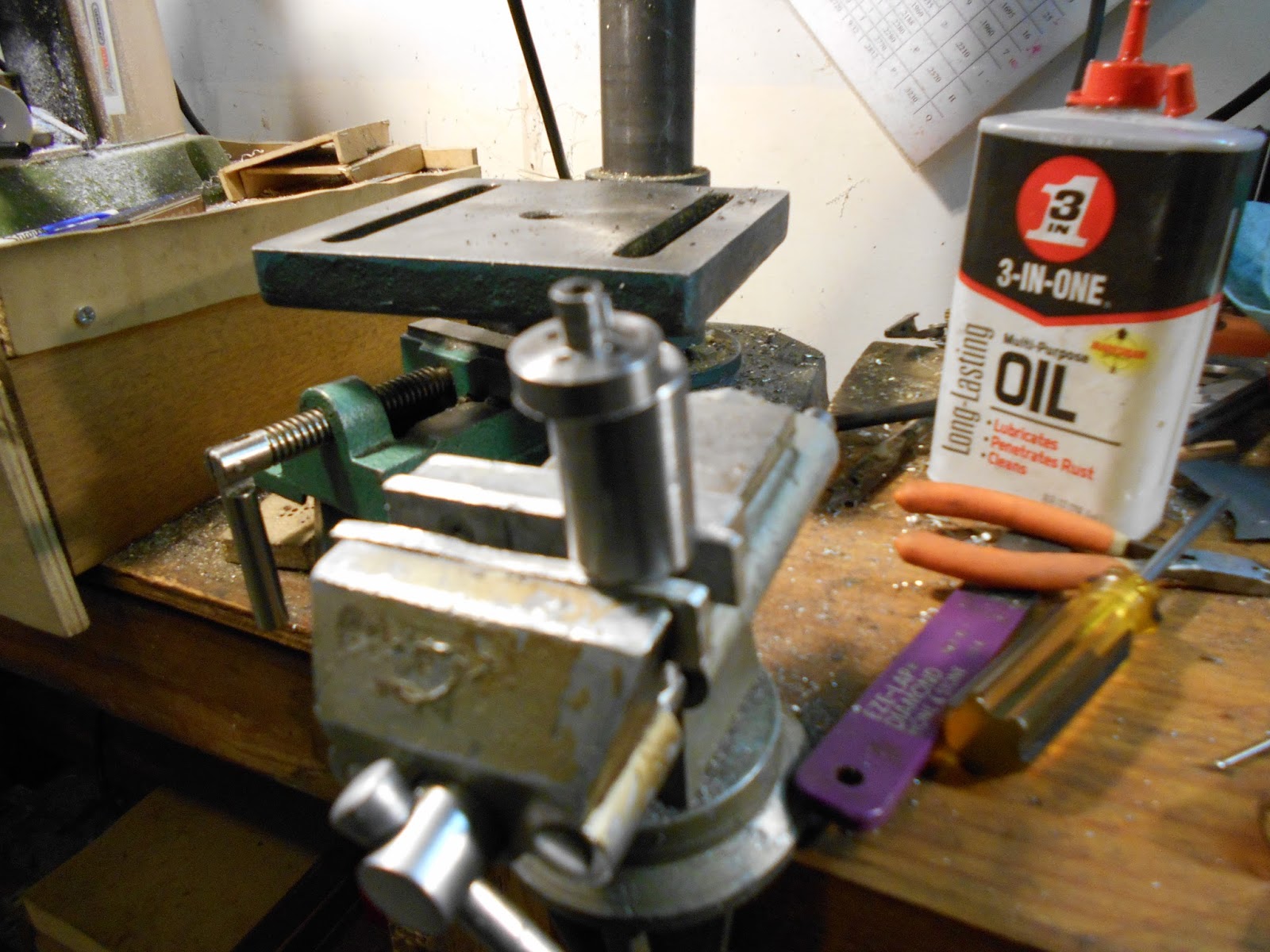
So with four holes in the blank, pick one, put the center hole into the screw, put one hole in the pin, and you have the setup below. It looks off-center, does it not? It is. It is supposed to be. When we put the whole megilla into the lathe, we will turn sort of a square with round sides.


When you are doing this you have to be very careful with the depth of cut. I experimented with setting up dial indicators to do this.


Impossible. They don't make them small enough, and I have no room to fit everything in. So I made a stop. It took a day, well worth it.


The stop is a dovetail that fits the ways of the Taig, an has a screw for fine adjustment, unfortunately a 6-32 screw because it is difficult to find  metric screws this small (about 5mm) this small in Alaska.


Next job is to make a radius forming tool. This tool will form the radius (which has to be exact). I had not reckoned with Lowe's 3/4" "mild steel." It is made out of supermanium. I think Lowe's supplier slipped up that day, and threw in a round bar made out of Titanium SuperSteel, because I made this tool out of Dremel shanks, which I know can be hardened.


Now we mount this in the middle of a square .25" bar and mill off exactly half of the tool, leaving a very sharp edge. We did this on the mill. Note the gear sitting to the left. It's the one I haven't completed. We use this tool to form the radii on the cutter. Then we use this tool to cut the radii. The first few radius tools I made were eaten up by the Lowe's Supermanium. I finally resorted to a broken Proxxon endmill. Teutonic technology proved superior to supermanium. I got a radius, Crude, but good enough for practice purposes. Now let's cut off the waste. Dean et al. use a slitting saw, but I used a Dremel abrasive cutoff disk mounted on the mill.


This has the great advantage. You don't have to grind the cutter; the cutoff does it for you. My finished cutter has two good teeth on it, the others were ruined by stupid mistakes.


I have learned a lot from this. I think I can make my own cutters now. More to come. Pic of cutter bit blurry, new camera. Will improve.


Tuesday, December 1, 2015

Onwards with wheel cutting


In the saga of the Isaacs clock , we now go on to the big wheels. There are two 96-tooth wheels, and (I think) a 100 or maybe a 120 tooth wheel, the latter in extreme range of what I can turn on the lathe. I am now making the wheels out of Lexxan instead of acrylic. Acrylic shatters too easily. With our homemade fly cutter it was possible to cut the first 96-tooth gear. Note the masonite backup disk on the wheel, this helps damp out the cutting shock.


So on to the second one. First step is to turn the blank. I try to do a spare, but it is  not a good idea to turn them together because the turning process tends to melt the Lexxan and then you have two welded wheels, which is not a happy situation.


So this gear was (still is) mounted on the dividing head, and I have cut about 8 teeth, but gear cutting is an absolutely frustrating situation and you should only do it when you are wide awake and capable of extreme concentration. So I decided to take a break, and the disadvantage of this is that I will have to "pick up" the cut. So I have only half of the mill available.

Then I decided to take a break. I would make a multi-point cutter. Comercial cutters are made with very large holes. Maybe 7mm. My mill takes a 3mm arbor. So the cutters are a saga all by itself, which will be the subject of the next post.

Cutter-making requires an eccentric arbor. I will explain this more fully in the next post, but it involves turning off-center. But here's a shot of the making of the arbor, in case I forget to include it in the next post.


It has taken a week to get this thing up, thanks to Google for their user-friendly (hostile) interface with blogger. Sorry.


 and one 100-tooth wheel. The 100 toother is going to be a real deal.

Wednesday, November 4, 2015

A pantographic interlude, v0.1

The gear cutting business has gotten to me and I have laid it aside for a while, since the concentration required is a bit much. So I have started two new new projects. One is the gear cutter (more later I hope) and the other is Pantograph 0.1.

You will remember (or maybe not) the pantograph from another episode; the label is "pantograph."  It was a crude thing, inspired by Stefan Gotteswinter (look up his channel on YouTube). It was a sub-prototype. It was made of masonite, with expired Dremel tools as pivots. Call it v0.0.


This thing will give you 2:1, 4.1 and one other ratio, something like 1:37:1.
I got that idea from Guy Lautard, "Machinist's Bedside Reader" which you can look up.

I used sharpies for 0.0. But all that would do is paper. I'd like to do metal.
So  it is time for a new version, 0.1.  For this I used steel arms; the pivots are bolts, and just to start I used nuts on the bolts. But there is a new requirement. It has to accept a Dremel tool.

A Dremel tool has a threaded nose that can be attached to other things.  Unfortunately this thread is M19x2, and it is hard to produce such a thread, although if you had a screwcutting lathe you could make your own tap. Fortunately Dremel makes a chainsaw sharpener kit (awful, I tried it) but the adapter works perfectly well, M19x2. So  here is the skeleton of V0.1:


The arms are steel strap except the lower crosspiece which is aluminum. A piece of Al angle supports the chainsaw adapter, the thing on the middle of the aluminum bar. The pivots are now bolts and nuts, although that will change. Here  it is assembled, complete with workholder arrangement. (The crossbars and a couple of wedges). I am trying to engrave a piece of Ally scrap.


There are several problems with this setup. The workholding needs improvement. Maybe threaded inserts and toe clamps. The board is much too short, easily fixed. The worst problem is depth adjustment on the dremel. Too little depth and it won't cut at all. Too much and it digs in and won't cut either. I have slots cut in the angle support but that is cumbersome to adjust. I am pondering this one -- it is not trivial. A screw adjustment would be ideal and then I would have a cross between a mill and a pantograph. I could mill out odd shapes just like Stefan Gotteswinter does. We will see.


Tuesday, October 13, 2015

Divide and conquer. Maybe.

Well, it has been a while and I have not posted. Life gets in the way. In the last post I had tracked my wheel (gear) cutting problems down to to bent shaft in the dividing head. Since the dividing head is a Topsy project (she just growed) this is a retrofit and rather difficult.Below, I am checking the runout on one of the wheels. Just as large as ever it was, a whole mm. Nothing new. Nothing for it but to remake the shaft. Turning it is easy, but..


Thing about the shaft is the dimensions. One end has to fit the gear. That is 5mm right on the money; the printer I took apart to get these gears is that dimension. The other end has to be a duplicate of the Proxxon mill spindle. This is M8x0.75, also metric. So I remade the shaft. Here it is, parted off. Note I am using both my homemade steady rest and a Dremel tool to part off the 5mm end. This gives a nice clean cut and wil not distort the shaft. I claim a new parting-off method.


Now, the big job is to put a front support on the shaft. For this I used a piece of my lovely Aluminum block that I ordered from the Internet.


 The problem is that I have to bore the 8mm hole exactly in line with the original 5mm hole in the rear. Lacking a jig borer (they cost a fortune) I used a transfer punch, and the above lashup shows how I got it done.


A runout check shows that I am down to a runout of .30 mm or so. Not really good enough but better than the full mm I had to begin with. What I will have to do is to watch my depth of cut. The wheel is perfectly round as the lathe can get it; the dividing head has a wobble! By varying the depth of cut, maybe I can compensate for this. So the setup looks like this:


 The dividing head is bolted to the mill table and "trammed" i.e squared to the table. In the mill spindle is my homemade fly cutter.  Let's try a 50 tooth wheel, I have two of them to do. Result:


Eureka! I have a wheel. It was like pulling teeth. Literally. One mistake and the whole wheel is trash. And I made lots of mistakes. Acrylic is totally unforgiving of mistakes, say forgetting to lock the dividing head. It explodes.  So I have switched to Lexan, much more resilient.

In the next episode we will cut the big wheels.


Sunday, September 27, 2015

Termination dust, 2015

I see I have already posted on this phenomenon before, because I have created a label for "termination dust." In order to save you the trouble of searching this blog for that label, I will repeat myself, as Walt Whitman did indeed say.

In the old days, when a prospector's claim ran out, he would start getting dust instead of nuggets in his pan (or whatever system he was using), and this was termination dust. Claim done. So nature gives us a similar signal" summer done.


Unfortunately my zoom feature has ceased. I fear my camera has therefore deceased too. Well, out on the back porch, we can just see dawn, and snow dust on the Chugach range. But there it is. The Fireweed has folded up. The birches turn yellow. Winter is upon us. Part of the fun of living in Alaska. Here in suburbia I can't go out and cut firewood. But we must accept change. The year wheels.

Sunday, September 6, 2015

Dividing head woes

Things have been very awry. My clock wheels are in trouble. Fortunately they are acrylic, or I would be out a fortune. Problem is that while some of the teeth look fine, others have flat tops. After pondering this one for a while I finally came to the conclusion that the dividing head is running out. This means it isn't centered. It is wobbling. So let's check.


Observe my new elegant mini-dial indicator holder. It will hold both my Imperial supersensitive indicator (shown above) and a conventional DTI. It is being used to record the runout (wobble) on the wheel, which is is on a mandrel (shaft) held in a collet. These are my wonderful ER collets. They have essentially zero wobble.
 
 'Nother shot same thing, same results. Runout about .002" or about 4 "cents" (.04mm). Uh-oh. The wheel is quite acceptable for clockwork. Time to check the runout on the shaft of the dividing head. This is quite a production. The dividing head is mounted on the mill. This, except for the base, is made of non-ferrous metal, and the indicator base will not adhere. So I had left the vise on the mill. In it I clamped a piece of angle iron, aand the dial indicator will adhere to that!  So by now I had acquired a metric dial indicator, and checked the runout again. Horrors. A whole millimeter!
The runout is all in the shaft of the dividing head.


Then  I took the dividing head apart and checked its shaft. It needed no dail indicator to show it was bent. So I made a new one. I used my steady rest to hold things still. Here I am, parting offf the result. I claim a new method of parting off. I use my Dremel tool holder, one of the very fragile  cutoff wheels, and spin the lathe one way and the work i t'other. Got a nice clean part, and a very narrow kerf.


So the next thing was to do something about this. It is a very small dividing head, so my next idea was to add a new outboard support.  It is an aluminum block. Here it is under construction.

The results on divde head 2.0 are not encouraging. I measure the runout  on the new spindle:


It still comes to 30 cents. While better than a whole dollar it is not very good. Impasse. While I am figuring out what do do about this, I added a new feature to Cecil B. de Mille. Behold my Z-axis Digital Readout.


Just a super-cheap digital plastic caliper, a bit of angle aluminum, and some drill and tap, and now I know where my Z-axis is. Of course I can always use the dials. But the Count himself (on Sesame Street) would get confused  by the number of turns you made. And one turn off is a whole millimeter off. Worthwhile addition.


Sunday, August 23, 2015

Big wheels on a small lathe

No matter how large a lathe you have, sooner or later you will come up with something too bigto turn. When I went to module 0.9 on the clock, I calculated the size of the biggest wheel and found I could swing it (that is, get it on the lathe without colliding with the bed). So I said, let us go ahead and do this thing with module 0.9. The following picture is the 50 tooth gears made so far. None of them are stellar. So we foresee problems ahead.


First thing was to cut the blanks out for the midsize wheels. I did this on the bandsaw. The first thing I did was to cut out masonite-type board slightly smaller than than the gear itself. When I put it on the lathe, it was very obvious that the regular toolpost was not going to reach to the rim and cut it. Impasse. Next morning I started designing a fixture that would move the toolpost -- and realized as I did I already had one, the compound slide. The Taig compound is very flimsy, so I usually don't use it unless I have to cut tapers. So up with the compound and success:


plus I have an extra 25 mm (1") by moving the tool to the outside groove.

So the last problem was to make a new dividing head plate. I did this my usual way, with my PostScript program. I used my optical center punch. Then off to the drill press. Just to make sure everything was centered, I used a fixture.


Then I put the dividing head back together and tried some more 50 tooth blanks.  None of them were stellar either. There is something wrong with the dividing head. But that will wait until the next episode.

Sunday, August 9, 2015

Change of pace: this year's garden

One of the problems of living in suburbia is the lack of space to put in a garden. Another, for me, was the less than sterling health. But I seem to be unable to live without planting something. So this year, willy-nilly, I put a garden on the back porch.


Front to back, we have radishes, spinach, mesclun (lettuce mix), red leaf lettuce and tomatoes. We have aready picked some of them and they are delicious.


As you see the tomatoes are actually tomatoing. I am not sure they will ripen. But they are certainly happy, and that is what counts.

I suppose I am a farmer at heart.I like to grow things you can eat. Even if my farm is now the back porch, and wait til next year when I will get some more real estate. It is now container gardening time.

We will return to our regularly shceduled clockmaking drama in the next episode.

Tuesday, July 28, 2015

Life at module 0.9

In the last episode, we nade some lantern pinions. Measurement revealed that they were actually module 0.9. So this is really a  blessing. Since I am making my own cutters, the larger module will be easier to work with. So I am now embarking on the process of cutting the wheels. The first problem is to make the cutter.  I use Dremel 3mm tool shanks from expended Dremel tool cutters. Cheap, and they are good steel. they can be hardened and tempered. I am making a fly cutter, a one-point cutting tool.

Now a fly cutter does not actually cut teeth. What it does is cut the space between teeth. A clock tooth is supposed to have a cycloidal profile. This is the profile generated by a circle rolling on another circle. Yuk. However, this is approximated by a straight cut with a "rounded  over" circular radius at the tip. The radius is something like 1.7 mm at module 0.9.

So as a first task I made a button gauge.


I turned down a piece of steel to the proper radius, say 1.7 mm. I am too tired to go consult my notes in the shop. I drilled two holes the proper distance apart. This was done on the mill, you could never hit it by eye. The button gauge will be used see if I am on target with the radius. There is the problem of depth of cut, but if I overdo this I can always grind it off. Off to the mill.

Here we have an expended Dremel shaft put into a homemade fixture, a piece of square stock with a setscrew to hold it in place. The fixture is clamped in the mill vise.


I have available 3mm, 2mm, and 1mm. end mills. These are diameters. Hmm. If I were to cut 1.7 radius I would need a 3.4 mm cutter. Unicorn. Uncomfortable. But the 3mm guy will go 1.5 mm aand for now that will do. It is quite difficult to center up the cutter. But above you see it taking shape. So I did this. Now we heat it up red hot and quench. This will harden the steel.


I use my handy furnace and water-quench, and then temper, a difficult job on a piece smaller than your little fingernail.

Having done this, we take a test cut on a leftover blank we happen to have. The diameter is completly off, we just want to see if the cutter works at all.


So I mount this random blank on the dividing head and cut a few teeth. The diameter is wacky. But it does work -- i.e. it cuts teeth. Spacing all wrong of course.

Next step is to turn up a proper blank on the lathe. I cut them out on the bandsaw. The scrollsaw would be better, but it melts the plastic so the bandsaw wins.


Now we can cut teeth properly. I did a whole bunch of them. There are so many errors you can make. You can forget to tighten the dividing head, for instance. This will chew the blank. You can forget to loosen the dividing head, which will mean slippage in the gear train. Maybe I should loctite the worm. But I don't want to do this yet.

Anyway, at the end of several days work,  I came up with some wheels.


The leftmost wheel is complete chowder, as Tom Lipton would say. As we go left to right, we see gradual improvement, as I correct my mistakes, so the rightmost wheel is almost usable. But there are two problems. The tooth profile is off. Also the spacing is irregular. The tooth widths vary. This is a problem with my homemade dividing plate. In the next episode we del with these problems.


Sunday, July 12, 2015

The saga of the lantern pinions

In a clock, the gears that convert the movement of the pendulum to the movement of the hands are of two types. If the gear  has 12 teeth or less it is called a pinion. If it has more than that, it is called a wheel. The Isaacs clock has 8 toothed gears for the pinions and other numbers for the wheels. Pinions are small fiddly things, about 6mm diameter. That's about 1/4" for the metrically challenged. Now there are several ways of doing pinions. First is to buy a commercial pinion cutter. Messrs. Thornton in England will sell you one, at what I consider an exorbitant price, 40 quid or about $80. Second, make tour own pinion cutter. I am really challenged here, because my mill is a real micro. The largest collet it will take is 3.2 mm (1/8") so the  7mm diameter of the hole in Messrs. Thornton's cutters is far too big for my tiny Proxxon mill. Second, make your own cutter. I looked a lot into this and they are quite a complex problem -- again because I have such a tiny mill. I will deal with this some other day. I can do it, I think, but I will have to rescale a lot of things.

The third way is to make lantern pinions and this is what I did. Essentially a lantern pinion is a very small hamster cage. It is two circles for the side of the cage, and 8 bars to the cage. Eight bars work out conveniently to 45 degrees at a side.


So I made up a wheel divided into 45 degree increments. A production,  but possible. I then used my aformentioned Dremel tool holder to drill the 8 holes. Simple, eh? Not really. First I had to make a mandrel, a shaft that fits into my "crocodile," the ER-16 collet on my Taig. I threaded it US 4-40 because that is the smallest tap and die set I own, about 2.4 mm. Then I had to make a special nut to fit the 4-40 thread and not interfere with the boring of the holes. A standard 4-40 nut is too big. The diameter of the hamster cage is 6.1 mm at module 0.6.

So now we turn up a bunch of hamster cage circles to the proper diameter, which is about 12mm. This can be done en masse, four sides at once. Then I laboriously cut up some music wire into cage bars. Regardless of its name, music wire has nothing to do with music, and worse, it is often called piano wire, although it has little or nothing to do with pianos.


The first result is shown above. It is a valid lantern pinion. It is sitting on top of a ski wax container. I use the ski wax on bandsaw blades and it really helps.

Now I made up an index stop out of an old saw blade and a broken Dremel mini-drill. I have lots of those, they are are very easy to break. The ones I am using are about 0.7 mm but unfortunately the wire is 0,77 mm.
The index stop is saw blade attached to a magnet., super-glued to the saw blade. I works.


And fortunately, looking through my supplies, I found a wire (from Michael's) same gauge as the music wire, slightly less stiff, and far less expensive. And much more obtainable. I have bought out Lowe's supply.

So here is the final mise en scene (forgive the lack of a grave accent). These are the tools I used to make 9 lantern pinions. I should only need 7, but better safe than sorry. There are pliers, of course. Then is my Archimedes drill. This has a piece of music wire in it, which is used as a drill/reamer to bring the holes in the cages to final size. It was quite a feat to grind that thing properly so that it would actually drill.


 There is an 8mm wrench that belongs to the mill. I use it to cinch up the pin vise, the invaluable object on the right, which holds the wire while you get it through the holes. Sitting in the pin vise is the last of the hamster cages.

When it was all over I measured the diameter of the pins in the cage. It was supposed to be 6.11 mm and came out to 7.7mm. Ouch! This is a major blunder. A real Bozo, as Tom Lipton would say. However I think it is a blessing disguised as a blunder. I worked out what the module actually is, and is 0.9 instead of 0.6. I think this module will be much easier to work with. Of course I will be into a redesign of the clock because the spacings will be different from the plans. But since I can calculate all of this, the redesign will not be too bad a deal. I can still swing the biggest wheel on the Taig. Stay tuned.


Sunday, July 5, 2015

A bookcase for the shop

It ocurred to me that it would be an excellent idea to have a bookcase in the shop. I have some books to which I often refer. Notice that I did not end a sentence with a preposition. Notice that it sounds clumsy to modern ears. Anyway,  I was inspired by Paul Seller's work. If you search for him, you will find everything. But Paul's YouTube videos deal with hand tools only. Just my ticket. So I went to Home Depot  (by accident, because I was looking for somehing else) and found a nice piece of cedar, sold as fencing and very cheap. About $1.69 as I recall. I decided I would use it as a bookcase and as a box for my dividing head. I lopped off what I needed for the case and that left me with some cedar. I planed it off, an excellent cardio exercise. So I want a dovetail case.

 I realized ex post facto that I should have done this backwards. You see above I am cutting pins in the uprights, Should have cut the tails instead. Simply a matter of appearance, joint is the same. One of Mr Seller's most interesting ideas is that of the "knife wall" and it did manage that correctly. When it came to putting it together it was another thing, I erred. Still, it came out all right. Not perfect. But 'twill suffice. Hand tools only for this thing.


So now it holds my essential references, and I am happy with that.

Back to the clock,  but that was a pleasant interlude.Coming next: making lantern pinions for the clock,


Tuesday, June 16, 2015

The .444 Magnum Oscillating Engine

I got tired of cutting clock wheeels and badly needed a vactaion sooo....

One of the first projects the beginning "model Engineer" does is an oscillating engine. These are very simple engines, where the cylinder oscillates back and forth to expose the intake and exhaust ports. A complete video of a build of an "Ossie" (as these things are called) engine will be found on Emma Ritson's channel on YouTube, if you want  to see a blow-by-blow description.

What had been holding me up was the lack of suitable material to build the cylinder.  But I found, still at Chalupy (which has probably burned to the ground by now, there is  huge forest fire there) an expended .444 Marlin cartridge  case. This is cylindrical, no necking at all, so it seemed like a possible candidate. A test with calipers yields 10.47 mm and the drawings call for 10mm. Close enough. In this build I have followed Mr Stan Bray's book, "Simple Steam Engines" and I must say both the words and the music (drawings and instructions) leave something to be desired.

Anyway, while I was at it I built a finger plate. This is a gadget to hold things down while you drill or otherwise machine them. It is a piece of aluminum with holes drilled in them. I got the idea from Clickspring's Channel on YouTube. It has a 45 deg  groove in it, which I did by tilting the block 45 deg in the vise and using an end mill.


So, a bit of Aluminum later, we have a finger block.


Next thing to so is to mark put the port face, which will be soldered to the cylinder. [In retrospect, I should have not done this. I should have bored out the cylinder and made the piston fit it. I also should have drilled the pivot, but not the port hole. I plead just following directions in the book.]
You see the finger plate in action.


So next we solder the cylinder to the port block. This went very well.


I turned a rod out of a Dremel tool shank. These need to be turned down to 3mm and threaded. They are around 3.2 mm so it is delicate. The only 3mm tap and die set I have happens to be M3x0.5 so that's what it got. Both ends. This is the pivot shaft; the pivot will rock about this.


Next job is the frame. I took some pains to line it up. It is very fortunate that Ossies are very forgiving.


Then I drilled the port hole intake and exhaust ports. They are tiny, about 1.5 mm. Then I made some more little fiddly parts (go see Emma's video) And  then I discovered the holes would not line up. In fact the piston would not go in all the way. I soldered the original port block hole up.


So I had to bore out the cylinder. Of course. It is an expended cartridge. Who knows what egg-shaped sections lurk in the heart of an expended cartridge? Had I done this in the first place, I would have saved a lot of time. In a limp excuse, brass is unobtainium in Alaska, except for cartridger, expended of course. The problem was indicating it. Because the port block has already been soldered I canonly indicate 2/3 of the diameter. I put up the 4-jaw chuck and did what I could.

So I turned a piston and voila, Marlon the .444 Magnum repurposed.


Still not right. Of course. The original called for a much thicker port block than I have. The piston was too short and the port holes would not line up. So I turned a new piston. Here is Version 0.2.

BTW Cecil B. De Mille is excellent for spacing accurately placed holes.


 Today I drilled the hole in the port block. It seems to work.

So here we are. I will return, I hope.