By now you are well aware of my current obsession with clocks. Our wooden clock is in the capable hands of John, who is finishing my wooden stuff. There is very little left to do on it. Actually there is quite a bit; but it is not difficult. So I have cast around for a new clock. I found the Isaacs Clock. This is a beginner's clock, and I am really the rankest beginner. I found it on the fascinating Dean's website. I am now tooling up for the Isaacs clock.
Lot of stuff there. Look for Dean's clock project. Not the least of the atttractions of this project is that I can do it on my Taig lathe. The original article is under the Yahoo horology group. I went and found the article. It is scan (not always very good) of an article which appeared in Model Engineer, date unknown, by the looks of it. I downloaded the article, in about nine parts. After a cursory scan, it was immediately obvious that to cut the wheels (gears) on this thing I would need a new dividing plate. I needed 100, 96, and 30 holes. So my first job was to make a new dividing plate.
There is a lot of stuff on making dividing plates. A dividing plate is an indexing device. It allows you to rotate something by a very carefully calculated amount. The big boys use worm and gear dividing heads. This is a very expensive alternative. I use a PostScript program that I wrote long ago to give me a paper template. I paste the template on to the final material. Some people use brass. If I could find it in Alaska at all, I would use it. But it is Unobtainium in Alaska. So I use Acrylic. I have a large supply of some stuff I found thrown away, long ago. I made the inner ring 60 holes. A very useful set of holes. For 30 holes I use every other hole of the inner ring.
I then paste the template on the acrylic. Cut it to rough shape. Using my faithful Veritas optical center punch (q,g.) , I centerpunch the holes. Then with great care I drill 1.5mm holes in the plate. Hint: keep the paper side up. Else you will get a distorting lens effect, caused by the fact that acrylic is transparent.
Next job. This is complicated. We have to make a cutter for the gear teeth. But in order to make the cutter we have to make a jig to make the cutter. The first part of this jig is the base. Dean, above, used brass. Unobtainable. So I used a scrap piece of steel I picked up. You will not understand this at all unless you look at the article I followed, also at Dean's site.Maybe after you look at it you will still not understand it, but for sure I will not duplicate Dean's crystal-clear instructions.
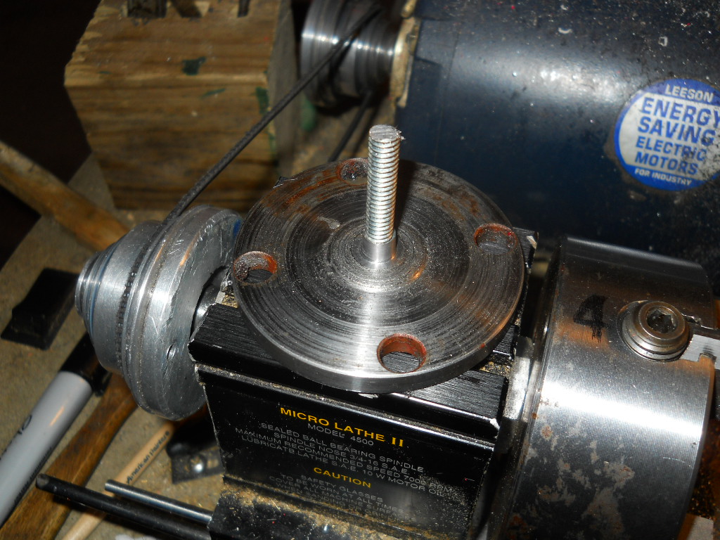
Here I have turned the piece of scrap to a nice round shape. It was not easy. After that, drilled a hole in the middle of it (and each of these steps is quite an oddysey) and tapped it. Due to the fact we live in Gringo-land I used a 1/4-20 tap, I wish I had 6mm x1 instead, and stuck a piece of threaded rod in it, and put a nut on top of it. The threaded rod and nut are hardware store stuff. Next step a bit harder.
Got to turn down nut thing round. To what diameter? Well, I looked at what was around on the web. Dean pointed me to an article by one Mr Creed, who may be found on the Yahoo Horology group, I believe. In this article, Mr Creed suggested 7mm diameter. Most commercial cutters use this diameter. OK, said I. A fateful decision. Above I have turned the nut down to 7 mm. The base is complete. Or so I thought.
Never that simple. But that is another post.
See through the trees
5 weeks ago


No comments:
Post a Comment