Thursday, May 23, 2013

Spring is here. Well, maybe not so much

It has been an extremely long winter. Then again, human memory for climate is short. Perhaps 30 years. I had a professor, long ago. Dr Helmut Landsberg. Prof. Landsberg had actually studied the human memory for meteorological events, such as hurricanes, floods, and even seasonal changes. That's whence I got the thirty year thing. We have a very selective filter, and anything intergenerational escapes it.

But this has been the slowest spring I have seen since I came to Alaska in 1999. Today I did a photo-op on our spring. First thing I did was go out to the garden. It is traditional in Alaska to plant on Memorial day. Not so much, this year. So I did a photo-op on it.
 First thing I did was to go to the garden. First, you can see the snow still on the ground in the background. Second, the garden is muck. I sank in 3 cm. No way I am planting this weekend. What fell effects this may have on my internal economy remains to be seen. Short growing season!
 
 Next we have the driveway. It is clear, but you see that snow patches linger on. Substantial snow patches. Bummer! I have never seen that much snow on the ground this late. Onwards.
Basargin loop, on which I live -- and have to maintain -- is a morass. It can be passed with 4x4 but is very iffy. But there is worse. There is the Basargin Road tank trap, a photo of which appears below.
At least we will have no Panzers coming through any time soon. The tank trap is impassable -- absolutely impassable-- by any vehicle  with less than 30 cm ground clearance.  Holes too deep. This excludes poor Vicky Vitara from making the passage. Notice that the villagers have dumped scrap wood all over the place in a futile attempt to improve things.  Notice the low-clearance car prudently parked on the Goat farm property. Neil is no fool! The only solution I can see is to corduroy the tank trap. One would cut logs to road width and put them down in close contact. This is a major undertaking. It involves chain saws and a lot of backbreaking manual labor, putting the logs in close contact. It is easier to let Ma Nature do the work and dry it out.  That is not happening with any speed.

However, this week I abandoned clocks and did some bicycle repair work.  I now have two functional bikes. This winter, the machine shed collapsed on one of my bikes (the best one, of course) and turned the rear wheel into a pretzel. I salvaged the axle and put it on my second bike, which had a broken axle. So not all a loss, and I am learning a lot about bicycle repair. More later, of course. I hope.


Tuesday, May 14, 2013

Creeping up on a new clock

First of all you should be aware that the wooden clock is alive and well. It is being finished at John's cabable hands. There are a whole bunch of fiddly parts that have to be finished.And there is still the pendulum, and the weight, and the pulleys. Lots of stuff to do. The backbreaking work is over, though.

But until they are finished, I can't work on anything else. So, as I have said before, I am jump-starting my next clock. This is the Isaacs clock.

The real problem with making clocks is making the wheels, i.e. gears. The real problem with making wheels is the wheel cutters. So since my last post I have been obsessed with making cutters, I am following a page which I supplied before, so I will not bore you with the details. I will say that it has been quite difficult. Now you could order these cutters form Mssrs. P.P Thornton in the UK for a modest 40 UKP apiece. Gulp. No. I must make my own cutters.

The cutters in question are described in Dean's pages, which I linked before. THe trouble is actually cutting them. Of course, I am not using "1/8 tool steel" as Dean suggests, because this is Unobtanium in Alaska. So I am using an old lawnmower blade. Very tough stuff.  It resists even my carbide tools. Plus it is an interrupted cut. The lathe tool cuts only sometimes. Since it it made on an eccentric arbor, that is, the center of rotation does not coincide with the center of the tool, it is very difficult even with carbide tools, which is what I am using. I persevered. I learned. Next time I will use my newly acquired angle grinder to rough the thing out. These things are at the extreme limit of the Taig lathe.

In the meantime, I read, on a clockmaking forum, of the equipment of some fellow clockmackers. This included a gentleman with an 18" South Bend lathe. That's about 450 mm swing and would have breezed through the cuts that strained my 55 mm lathe. Wish I had an 18" South Bend. "I like to take big cuts," said the owner.

But eventually, about a week or so later, I wound up with a cutter blank.
This image is a little confusing. There are four holes filled in with JB-weld. They don't count. The ones that do count are really half-holes. Notice the shape of this thing. It is a sort of a square with rounded sides. That is the effect of the eccentric arbor. The rounded sides provide relief.  See Dean's page, previously cited. It took forever to get to this point.

However, we got there. The next stage is to make a form tool to shape the cutter teeth.

This whole thing is unwinding the Industrial Revolution. You need A. But to make A you need to make B. But to make B, you need to make C... and so on.  Either that, or pay Mssrs. P. P Thornton Ltd. forty quid for one cutter. Ouch. I will make my own, and and a very interesting experience, too. A fine fate for a recycled lawnmower blade.

Saturday, May 4, 2013

Fixin' to get ready on a new clock

By now you are well aware of my current obsession with clocks. Our wooden clock is in the capable hands of John, who is finishing my wooden stuff. There is very little left to do on it. Actually there is quite a bit; but it is not difficult. So I have cast around for a new clock. I found the Isaacs Clock. This is a beginner's clock, and I am really the rankest beginner. I found it on the fascinating Dean's website. I am now tooling up for the Isaacs clock.


Lot of stuff there. Look for Dean's clock project. Not the least of the atttractions of this project is that I can do it on my Taig lathe. The original article is under the Yahoo horology group. I went and found the article. It is scan (not always very good) of an article which appeared in Model Engineer, date unknown, by the looks of it.  I downloaded the article, in about nine parts. After a cursory scan, it was immediately obvious that to cut the wheels (gears) on this thing I would need a new dividing plate. I needed 100, 96, and 30 holes. So my first job was to make a new dividing plate.

There is a lot of stuff on making dividing plates. A dividing plate is an indexing device. It allows you to rotate something by a very carefully calculated amount. The big boys use worm and gear dividing heads. This is a very expensive alternative. I use a PostScript program that I wrote long ago to give me a paper template. I paste the template on to the final material. Some people use brass. If I could find it in Alaska at all, I would use it. But it is Unobtainium in Alaska. So I use Acrylic. I have a large supply of some stuff I found thrown away, long ago.  I made the inner ring 60 holes. A very useful set of holes. For 30 holes I use every other hole of the inner ring.

I then paste the template on the acrylic. Cut it to rough shape. Using my faithful Veritas optical center punch (q,g.) , I centerpunch the holes. Then with great care I drill 1.5mm holes in the plate. Hint: keep the paper side up. Else you will get a distorting lens effect, caused by the fact that acrylic is transparent.

Next job. This is complicated. We have to make a cutter for the gear teeth. But in order to make the cutter we have to make a jig to make the cutter. The first part of this jig is the base. Dean, above, used brass. Unobtainable. So I used a scrap piece of steel I picked up. You will not understand this at all unless you look at the article I followed, also at Dean's site.Maybe after you look at it you will still not understand it, but for sure I will not duplicate Dean's crystal-clear instructions.

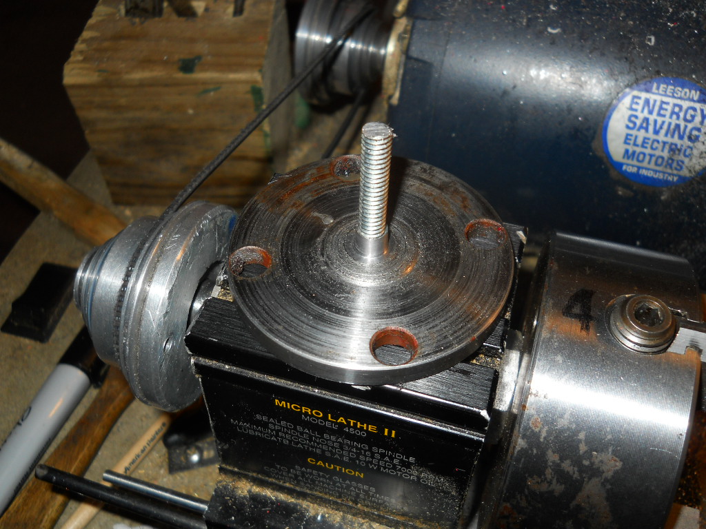
Here I have turned the piece of scrap to a nice round shape. It was not easy. After that, drilled a hole in the middle of it (and each of these steps is quite an oddysey)  and tapped it. Due to the fact we live in Gringo-land I used a 1/4-20 tap, I wish I had 6mm x1 instead, and stuck a piece of threaded rod in it, and put a nut on top of it. The threaded rod and nut are hardware store stuff. Next step a bit harder.

Got to turn down nut thing round. To what diameter? Well, I looked at what was around on the web. Dean pointed me to an article by one Mr Creed, who may be found on the Yahoo Horology group, I believe. In this article, Mr Creed suggested 7mm diameter. Most commercial cutters use this diameter. OK, said I. A fateful decision. Above I have turned the nut down to 7 mm.  The base is complete. Or so I thought.

Never that simple. But that is another post.


Saturday, April 27, 2013

The ground, the ground!

It seems spring has arrived. It was rather coy. It dumped a foot of snow in March, so we had an unusal amount of it around. But "breakup" as they call it in Alaska, seems to have arrived. I know it is breakup when I can see my driveway.
We should not be surprised, but I at least always am. Look! I can see some of the driveway! Behold! I can see the path to the door! We have not beheld this sight since December. The ground is bare. In places. It does seem to be melting. Nights still go below freezing. But we are getting there. Breakup is a frustrating season. Too much snow and slush to bike. Snow quality awful, can't ski. Can't garden. Snow on ground, and it is frozen anyway. Grr. So I have to walk. Trouble is I have taken all walks at least a thousand times. Nothing new here!

Well, there is always clockmaking. It will not be long before I inflict it on you again, so enjoy the respite.

Wednesday, April 17, 2013

Finishing a clock (literally)

The time has come, the walrus said, to speak of many things (Lewis Carrol, The Walrus and the Carpenter). And now we have to put on a spurt of effort and actually finish the thing. Literally. Among the major projects done since my last post, the biggest is the minute work. Clockspeak, of course. In my case this is a misnomer. The Center Wheel revolves at a majestic rate of one revolution per hour. Great thing for a minute hand! But, as you will immediately see, this is not really cool for the hour hand. In one hour, given our 12-hour dials, the hour hand has to go round 1/12 the distance. (12 hours in one half-day). So what to we do? Add more gears, of course. Now I had cut these gears on the bandsaw long ago. But now we have to depth the wheels and pinions.  Clockspeak rears its ugly head again. Remember, big gear is a wheel, small gear is a pinion. Depthing means make them run freely. Book recommends sandpaper. I found a better way. Mr Wilding didn't know about Dremel tools or he would have done this himself. Book published in 2002 or so.
 So I did something I should have done long ago. Live and learn. I measured the aperture between gear teeth, and it is close to or exactly 3mm. I searched my inventory of Dremel tool accessories and found a router bit very close to 3mm. I put the wheel into the Taig and the Dremel into my vertical milling attachment. With this setup I could shave 0.01 mm off the teeth, and shave them I did, running the Dremel at max. Saved hours of work. I used my 60-hole dividing head to position (index) the teeth. Forget sandpaper. It was very nice that these things are 30-tooth gears; my 60-hole dividing plate can handle them easily. Pinions done same way; again they fit my 60-hole dividing plate.

This bit done, the we are almost through the major work on the clock. So the big moment has arrived. The clock was taken apart. If you make a clock, you will soon learn that the fate of a clock is to be taken apart. I handed the clock over to John. He is to make it look pretty. He is very, very, good at that.

 Gulp. The paper patterns have been sanded off. I feel lost without my paper patterns. But go they must. So John got rid of them. My only spec was that the various wheels should have different colors. Here, John is staining the Center Wheel. Previously he has sanded it. Gone is the paper. Again, gulp.
 The plates look very nice in a much darker color. They have a certain character.
There are many details with which we have to deal. But amazing.  A piece of very cheap plywood turns out a very nice clock.

Endless details. I have to smooth out the escape wheel. I have to make the pendulum...  never mind. Progress is progress.

While all this is going on I am setting up to make my next clock. It will not be a wooden clock. And that is all I will say at this point. But clockmaking is not a hobby. It is an obsession.

Wednesday, April 3, 2013

Clock: escaping from reality

If all there were to a clock (wooden or otherwise) were a bunch of gears with a weight (or spring) attached, then it is probably pretty obvious that the falling weight would just unwind the gear train at the proper rate for whatever weight you put on it. Minus friction. So how does a clock keep time? It has to have an escape mechanism, clockspeak for a device that interrupts the weight on its Newton-ordained fall to the ground. The escape mechanism on a clock is usually, in a clock, based on a pendulum; since a pendulum of a given length gives you a very steady beat. But alas, there is friction. You can easily make a pendulum. Put a weight on the end of a rod. Put it in some sort of pivot. A nail, say. Push it. You will see that eventually the pendulum beats no more. Friction, you see. So there is another function the escape mechanism must perform. It has to give a bit of a kick to the pendulum, to counter-act the evil friction. Actually, friction can be a Good Thing (TM) else your car wouldn't stop when you hit the brakes, but in clocks we really, really, don't like it. Again in clockspeak, the bit of a kick is called impulsing the pendulum. Over the years, nay centuries, there have been numerous very clever humans who have designed escape mechanisms, as a Google search on "clock escape mechanisms" will convince you. Mine is what the designers of this clock deemed best, a "deadbeat escape mechanism". There are many others.
The basic escape mechanism consists of the anchor and the pallets.The anchor consists of a piece of wood. You can see the anchor very clearly in the pic above. It looks like an anchor! The pallets are pieces of brass. Resist wear, you see. It was fun making the pallets. I milled them on the lathe, but took no pictures because it was a very simple job. Then I filed to the required angles. Now I have to adjust them, but that will take time (it's a clock!) and I have postponed it. I moved on to that tedious job, the minute work as it is called. The thing is, the clock is set up (all those gears!) so the Center Wheel (one of the gears) revolves at 1/60 times a second, or in other words one minute. But there is an hour hand. It must go around the dial much slower than the minute hand. In fact it must go around 60 times slower. (assuming you have a 12-hour dial). More gears. That's what the minute work is for. Another gearbox. Now the wheels were cut out on a bandsaw by hand. Hardly precision work. Furthermore here are small imperfections caused by the fact that you did not drill the holes for the axles, or arbors, exactly where you should. So we have to depth the gears (wheels). In this clock, says Mr Wilding, this involves sanding off bits from the teeth until the gears spin freely. At first I tried sandpaper. Very slow. I spent three days depthing the wheels. Then I got smart. I rigged up my lathe with it Dremel milling jig, which I described elsewhere.


The Dremel has a router bit in it. With this baby I can take off as little as .01 cm (or .0005") at  one go from the wheel. (Not really. This is wood, not metal. Precision is futile). This speeded up the problem considerably. Couldn't have done this with the going train (the main gears) because the wheels are too big to "swing" on my little Taig. Later I got even smarter. But that's another post. Live and learn.


Thursday, March 28, 2013

So just when you thought you were immune from clocks, I have to return to them. I warned you. Clocks are an obsession. Great thing to do in the winter, though. have had a snowstorm and there is a new 40 cm on the snowpole! 

The above picture shows the center wheel. Mr Wilding (whose instructions I am following)  would spell it "centre wheel. " Engineers would say "gear" but I too bow to clockspeak. After all it has been around since the 16th century, if not longer. The pic shows one end of the center wheel.  Mr Wilding put steel ends on his wheel axes. Sound idea. Cut down on friction. Almost any clock plan you will find on the Internet has solid steel arbors (axles). The other end of this arbor is a point. Here I am turning the point on my trusty Taig lathe. I have finally learned how to turn points. It requires a contraption called a compound slide in the US and a top-slide in the UK. No matter, same thing. I could have done it with a file, but the compound is much faster. Good practice, too. Voila the point being turned. By the way, the things we are turning are called pivots in clockspeak. Bearings from where I come from.
 In Mr Wildings's modifications, the points run in brass bushings. A bushing is just a piece of something (my case, brass. And by the way it is very difficult to find brass in Alaska. Not a material in great demand here) with a hole in it. No big deal. However, the bushings must be reamed out to a 60 degree point to accept the points. Further, the holes you drill must accept the bushings as a tight fit. In fact you should press the bushings in. I used my drill press as, well, a press. This means that you cannot trust the hole sizes on the drawings. On the balance, this is not a clock for the amateur.  As the British say, the words do not match the music. For Mr Wilding, who has built more clocks than I have passed power poles, this is no problem. I have had a few problems matching up the two. If only he had corrected the drawings!

 Above, I am using a 60 deg reamer to ream out the bushings. No major problem there. Next problem is pushing the bushings into the "plates" of the clock. The   plates  are the frame of the clock. If you happen to use Mr Wilding's instuctions you will have drillled undersize. For pressing I use my drill press and brute force. I was careful to drill the holes undersize. A nuisance when it is all done, because I work metric and all my stock is Imperial i.e. RGU, but it can be done.

Here I am pressing the bushings into their holes.I used a 60 deg point. These babies are not coming out with any ease. Good.
 
The next step is to assemble the clock. Again Mr Wilding fails me. The drawinngs all use numbers, but Mr Wilding uses names (third wheel, fourth wheel, etc.). I  really wish  he had corrected the drawings. No matter.  Let's start assembling this thing. First thing in is the  escape wheel:                     
 And next, the third and fourth wheels. Which are obscure numbered parts on the drawings. Grr. I wish Mr Wilding had supplied corrected drawings! No insult to Mr Wilding, but this is my first clock, and the words don't match the music.
Looks like a clock, does'nt it? But alas, there are trials yet left. Although we carefully "depthed" the wheels, the thing sticks. It does not run freely. Lots of reasons, but most likely, when we drilled the holes for the arbors, we did not do it quite right and there are some sticky spots on the wheels. Stay tuned. The wheels must spin freely or we are lost. So back to square here minus one. More to come.

I note that most modern clock plans specify steel arbors. Running on hardwood bearing holes. Probably cheating! But much easier for a good woodworker than the stuff I am going through. And all in RGU, too. Drill 17/128th of an inch. Why oh why RGU?